Spindle tape tension device of ring spinning frame

A spindle tape and tension technology, which is applied to spinning machines, continuous winding spinning machines, textiles and papermaking, etc., can solve the problem of poor workmanship of support arms and adjustment frames, heavy hammer weight, and increased power consumption of the whole machine and other problems, to achieve the effect of changing the tension quickly and easily, the tension of the spindle tape is stable, and the mechanism is simple and reliable.

Inactive Publication Date: 2012-05-02
JINGWEI TEXTILE MASCH CO LTD
View PDF0 Cites 0 Cited by
  • Summary
  • Abstract
  • Description
  • Claims
  • Application Information

AI Technical Summary

Problems solved by technology

According to the calculation of 1200 spindles per spinning frame, 300 sets of spindle belt tension devices are needed. In order to ensure that the spindle belt does not fall off during operation, the spindle belt tension wheel needs to have a reasonable space position, and the support arm 24 and bracket bolts must be adjusted one by one. 25. Satisfy the front, rear, left, and right spatial positions of the spindle belt tension wheel 27; at the same time, the tension of the spindle belt depends on adjusting the position of the weight on the adjustment frame, and then tightening. There are thirteen scale positions on the adjustment frame, and the density is large , These are all adjusted by the workers during on-site installation, the workload is heavy, and it is difficult to do well, resulting in different positions of the tension pulley, inconsistent tension of the spindle belt, or even generally too large, and increased power consumption of the whole machine
In addition, the structure of the spindle tape tension device is complicated, the support arm and the adjustment frame are poor in workmanship, the distribution of the force arm is unreasonable, and the weight of the heavy hammer is required to meet the tension of the spindle tape. The cost of the whole machine is very high, which restricts the development of the spinning frame.

Method used


Image

  • Spindle tape tension device of ring spinning frame
  • Spindle tape tension device of ring spinning frame
  • Spindle tape tension device of ring spinning frame

Examples


Embodiment Construction

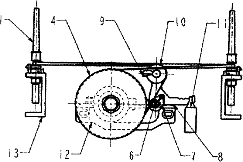
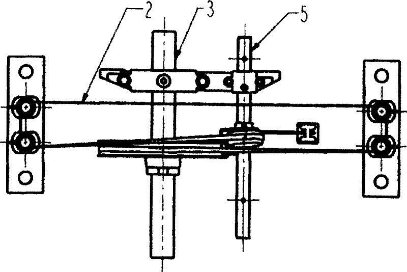
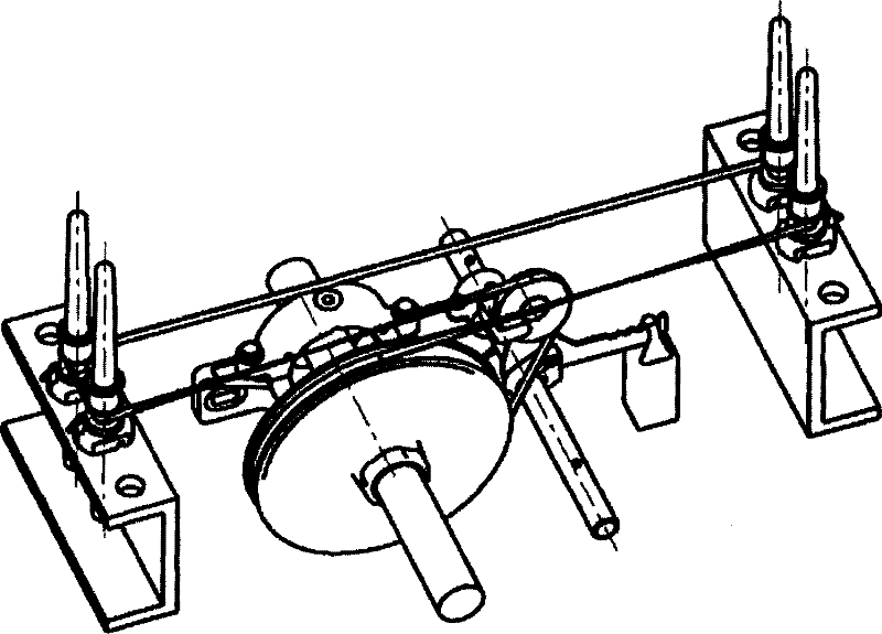
[0013] A spindle belt tensioning device for a ring spinning frame includes a spindle 1, a spindle belt 2, a main shaft 3, a rolling plate 4, a tension wheel shaft 5, a positioning pin 6, a support ring 7, a bracket 8, a tension wheel frame 9, and a spindle belt tension wheel 10 , heavy hammer 11, main shaft bearing seat 12 and dragon bar 13; main shaft 3 and tension wheel shaft 5 are set on main shaft bearing seat 12, rolling disc 4 is set on main shaft 3, positioning pin 6 is set on tension wheel shaft 5, supporting ring 7 Set on the tension wheel shaft 5 and positioning pin 6, the bracket 8 is set on the support ring 7, the weight 11 is set on one end of the bracket 8, the tension wheel frame 9 and the spindle belt tension wheel 10 are set on the other end of the bracket 8, the spindle 1 is arranged on the dragon tendon 13, and the spindle tape 2 is arranged on the rolling plate 4, the spindle tape tension wheel 10 and the four spindles 1.


PUM


Abstract

The invention relates to a spindle tape tension device of a ring spinning frame, wherein a main shaft (3) and a tension pulley shaft (5) are arranged on a main shaft bearing seat (12); a rolling disc (4) is arranged on the main shaft (3); a positioning pin (6) is arranged on the tension pulley shaft (5); a support ring (7) is arranged on the tension pulley shaft (5) and a positioning pin (6); a bracket (8) is arranged on the support ring (7); a heavy punch (11) is arranged at one end of the bracket (8); the tension pulley frame (9) and a spindle tape tension pulley (10) are arranged at the other end of the bracket (8); a spindle (1) is arranged on a keel (13); and a spindle tape (2) is arranged on the rolling disc (4), the spindle tape tension pulley (10) and four spindles (1). With the adoption of the spindle tape tension device, the requirements on tension stabilization and consistence of the spindle tape of the spinning frame can be met.

Description

technical field [0001] The invention belongs to a part of a textile machine, in particular to a tensioning device for a spindle belt of a ring spinning frame. Background technique [0002] The ring spinning frame is an important equipment with a large area and a wide range of production processes in the textile industry. Its performance directly affects the quality of the yarn, the amount of labor, the labor intensity of the workers, management, and economic benefits. The level directly affects the development of the cotton spinning industry. [0003] With the upgrading of the textile industry, users have higher and higher requirements for textile machinery. Spinning frame long car with collective doffing has become the mainstream in today's market. The number of spindles has gradually expanded, and the current maximum number of spindles has reached 1632 spindles. The spindle drive of the widely used ring spinning frame is driven by a single tension wheel with a group of ...

Claims


Application Information

Patent Timeline
Patent Type & Authority Patents(China)
IPC IPC(8): D01H1/241
Inventor 张新民师雅并张满枝谈叡石华睿李嘉琦侯少辉曾贵梅田克勤王建根刺志勇
Owner JINGWEI TEXTILE MASCH CO LTD
Why Eureka
Try Eureka