
Hydrogen purified recovery system and process method

A process method and hydrogen technology, applied in hydrogen separation and other directions, can solve problems such as energy and cooling liquid waste, and achieve the effect of reducing energy consumption, avoiding waste and reducing energy consumption

Inactive Publication Date: 2011-04-20
苏州市创新净化有限公司
View PDF4 Cites 6 Cited by
  • Summary
  • Abstract
  • Description
  • Claims
  • Application Information

AI Technical Summary

Problems solved by technology

[0002] In the existing hydrogen purification and recovery process, the raw hydrogen is firstly filtered to remove dust, then enters the buffer tank for buffering, and then is compressed and heated by a compressor. The compressed hydrogen usually reaches about 100 degrees, and then is cooled by water through a cooler to After being heated by a heater at room temperature, it enters the deaeration tower. In the deaeration tower, the hydrogen-oxygen reaction deoxygenation usually requires a higher temperature, so a heater needs to be installed in the deaeration tower. The compressor is usually bound together with the cooler, so that although the output pressurized gas is guaranteed to be at normal temperature, in this process, energy and cooling liquid will be wasted

Method used


Image

  • Hydrogen purified recovery system and process method
  • Hydrogen purified recovery system and process method

Examples


Embodiment Construction

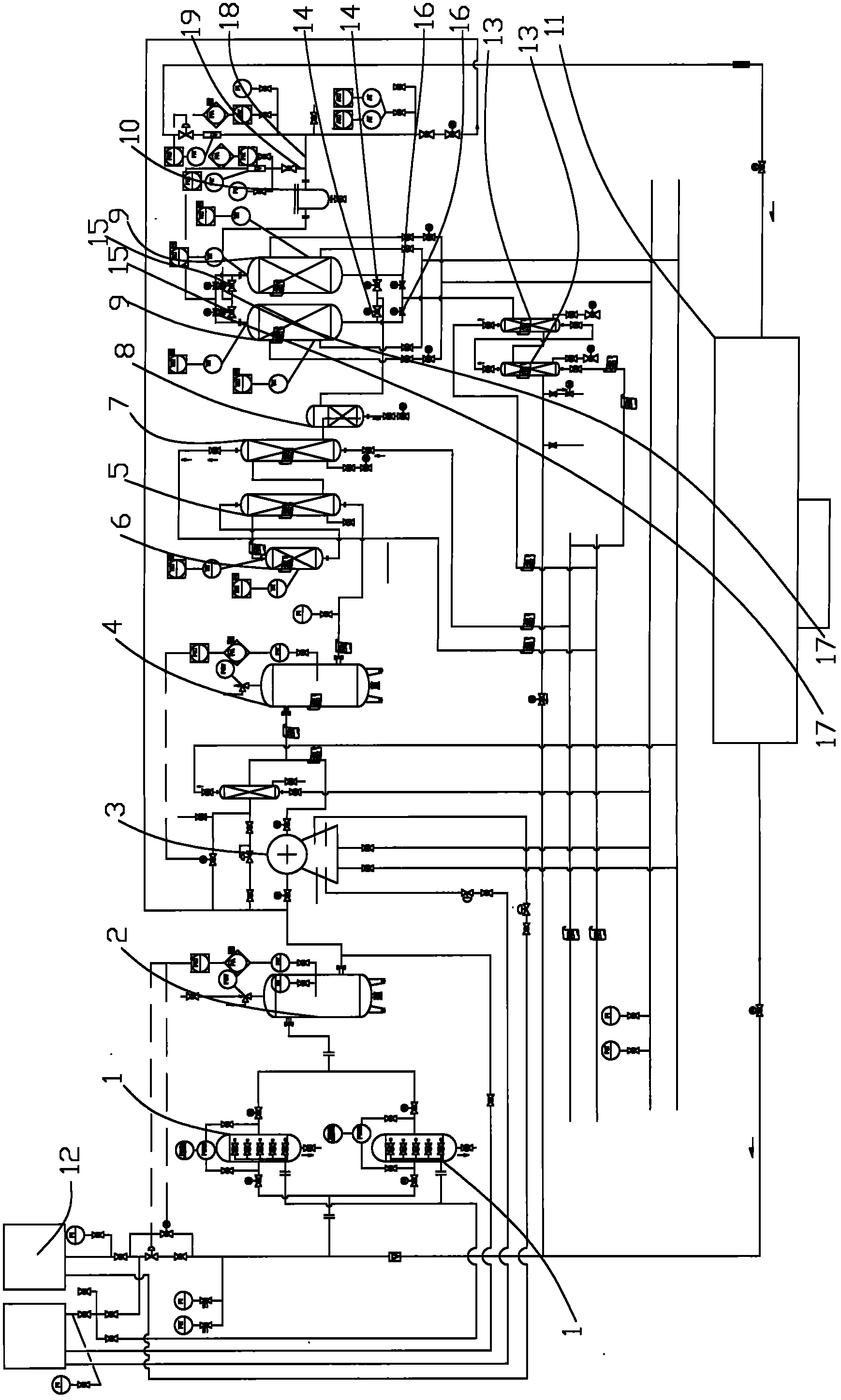
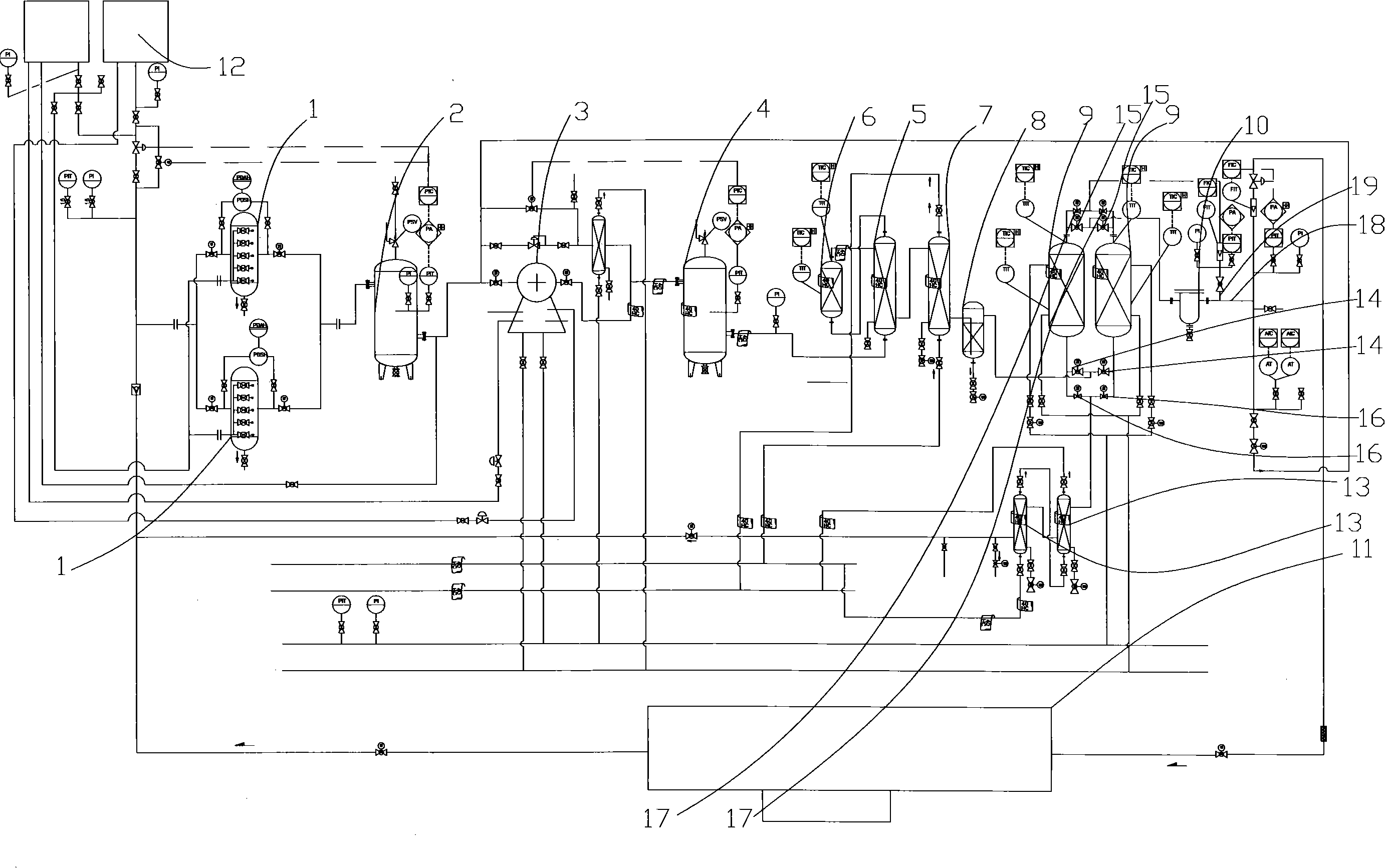
[0018] The structure of the present invention will be further described below in conjunction with the accompanying drawings.

[0019] see figure 1 As shown, the hydrogen purification and recovery system includes a dust removal filter 1, a first buffer tank 2 whose inlet can be communicated with the output port of the dust removal filter 1, and a hydrogen compressor 3 whose inlet can be communicated with the outlet of the first buffer tank 2 , the second buffer tank 4 whose inlet can be connected with the outlet of the hydrogen compressor 3, the heat exchanger 5 having the inlet and outlet of the low-temperature medium and the inlet and outlet of the high-temperature medium and the inlet of the low-temperature medium can be connected with the outlet of the second buffer tank 4, The inlet can be connected to the outlet of the low-temperature medium of the heat exchanger 5 and the outlet can be connected to the deaerator tower 6 connected to the inlet of the high-temperature medi...


PUM


Abstract

The invention discloses a hydrogen purified recovery system and process method. The raw material hydrogen is filtered and dedusted through a dedusting filter, and is buffered by a first buffer tank, then is compressed and heated by a hydrogen compressor, is buffered by a second buffer tank, enters into a deoxidizing column through a heat exchanger and then is deoxidized by the deoxidizing column;the heated hydrogen is compressed by the hydrogen compressor for reducing the energy consumption of the heater in the deoxidized column; after exchanging heat with doxidized hydrogen and then being heated in the heat exchanger, the hydrogen, which is compressed and heated by the hydrogen compressor, enters the deoxidizing column for deoxidizing; as previously mentioned, the temperature in the deoxidizing column is higher, the deoxidized hydrogen has higher temperature; the energy consumption of the heater is lowered by carrying out heat exchange on the hydrogen before being deoxidized in the heat exchanger; the needed amount of the cooling liquid in a subsequent cooler is lowered by lowering the temperature of the deoxidized hydrogen, thus avoiding the waste of the cooling liquid; and thehydrogen and the water are separated through a steam-water separator after the deoxidized hydrogen is cooled by a cooler, and the hydrogen is dried by a dryer, and is filtered and dedusted through a filter collector to obtain the purified gas. By utilizing the hydrogen purified recovery system and the process method, the energy consumption can be reduced, and the waste of the cooling liquid can be avoided.

Description

technical field [0001] The invention relates to a hydrogen purification and recovery system, and also relates to a working method of the system. Background technique [0002] In the existing hydrogen purification and recovery process, the raw hydrogen is firstly filtered to remove dust, then enters the buffer tank for buffering, and then is compressed and heated by a compressor. The compressed hydrogen usually reaches about 100 degrees, and then is cooled by water through a cooler to After being heated by a heater at room temperature, it enters the deaeration tower. In the deaeration tower, the hydrogen-oxygen reaction deoxygenation usually requires a higher temperature, so a heater needs to be installed in the deaeration tower. The compressor is usually bound together with the cooler, which ensures that the output pressurized gas is at normal temperature, but in this process, energy and cooling liquid will be wasted. Contents of the invention [0003] The first object of...

Claims


Application Information

Patent Timeline
IPC IPC(8): C01B3/50
Inventor 张文波颜庭勇尹泉生张敬成
Owner 苏州市创新净化有限公司
Learn More