Method for electroplating wire-drawing terminal

A terminal and wire-type technology, applied in the field of electroplating of draw-wire terminals, can solve the problems of waste of metal plating materials, unable to locate reference, inaccurate electroplating, etc., and achieve the effect of reducing production costs

Inactive Publication Date: 2012-09-19
DEYI PRECISION ELECTRONIC IND CO LTD PANYU
View PDF0 Cites 0 Cited by
  • Summary
  • Abstract
  • Description
  • Claims
  • Application Information

AI Technical Summary

Problems solved by technology

[0004] However, when the traditional wire-drawing terminal is partially electroplated on the contact area, due to the smooth surface of the wire-drawing terminal, no positioning reference can be found during electroplating, so it cannot be accurately plated to the contact area. Therefore, it is forced to use immersion plating for electroplating, that is, the entire wire-drawing terminal is electroplated, so that other surface areas of the wire-drawing terminal except the contact area are also plated with the metal plating material, Thereby causing the waste of described metal plating material, and thus increased the production cost of product

Method used


Image

  • Method for electroplating wire-drawing terminal
  • Method for electroplating wire-drawing terminal
  • Method for electroplating wire-drawing terminal

Examples


Embodiment Construction

[0031] In order to facilitate a better understanding of the purpose, structure, features and effects of the present invention, the electroplating method of the wire-drawing terminal of the present invention will be further described in conjunction with the accompanying drawings and specific embodiments.

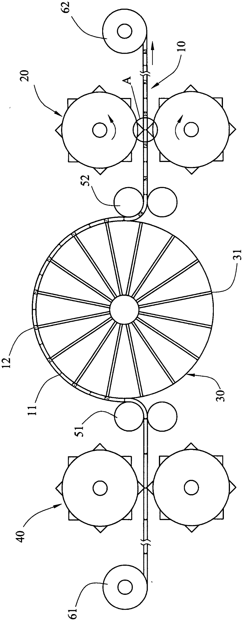
[0032] Please refer to figure 1 , is the first embodiment of the electroplating method for a wire-drawing terminal of the present invention, which includes a wire 10 and an electroplating machine (not labeled).

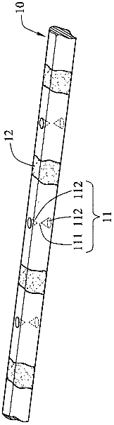
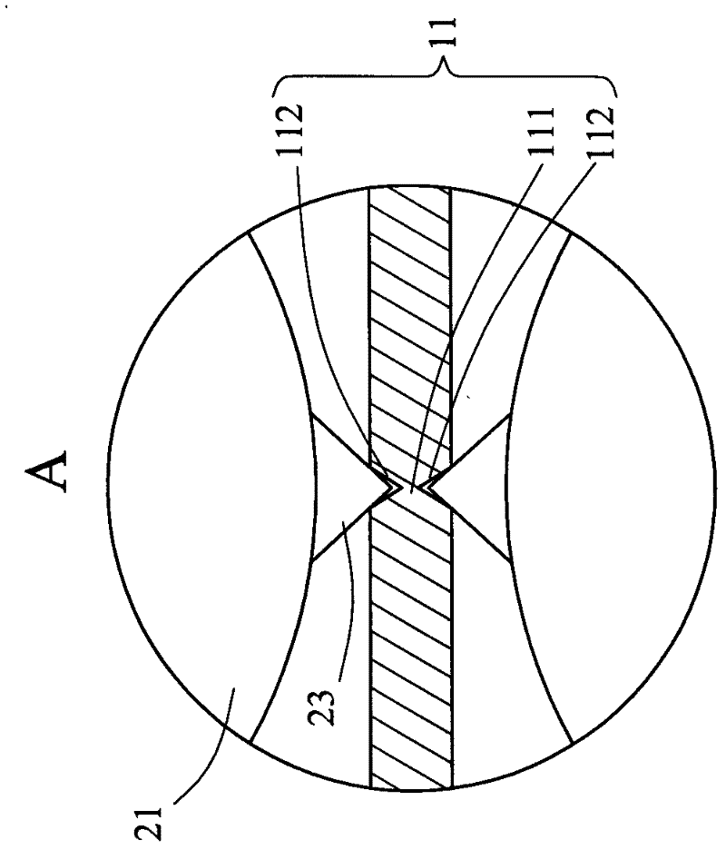
[0033] Please refer to figure 2 , the surface of the wire 10 defines a plurality of pre-plating areas (unlabeled) at intervals, and is provided with a plurality of positioning grooves 11 at intervals, and the plurality of positioning grooves 11 are equidistantly arranged on the wire 10 and distributed on the same straight line , it is convenient to provide a positioning reference for the pre-plating area (not labeled). The positioning groove 11 is provided with an...


PUM


Abstract

The invention discloses a method for electroplating a wire-drawing terminal, relating to a wire rod and an electroplating machine, wherein the surface of the wire rod is defined with a plurality of pre-electroplating areas at intervals, the wire rod is provided with a plurality of locating slots at intervals, and the locating slots are arranged on the wire rod at equal intervals; and the electroplating machine is provided with an electroplating operation part and a driving mechanism, the driving mechanism is used for bearing the wire rod to travel via one transmission route of the electroplating operation part along the row, and the driving mechanism comprises at least one driving block for corresponding to the locating slots on the wire rod so as to drive the wire rod to do propelling movement. Compared with the prior art, because the locating slots are arranged at equal intervals, the method provided by the invention has the advantage that the pre-electroplating areas have locating references in the electroplating process; and by controlling the operating speed of the driving mechanism, the electroplating operation part can accurately electroplate the pre-electroplating areas tolocally electroplate the wire rod, thus realizing the purpose of locally electroplating the wire-drawing terminal.

Description

[0001] 【Technical field】 [0002] The invention relates to an electroplating method for a wire-drawing terminal, in particular to an electroplating method for partially electroplating a wire-drawing terminal. 【technical background】 [0003] Usually a terminal has a contact area for electrical contact with electronic components. In order to improve the electrical connection characteristics of the contact area and enhance its corrosion resistance and wear resistance, metal plating can be applied to the contact area of ​​the terminal. material. [0004] However, when the traditional wire-drawing terminal is partially electroplated on the contact area, due to the smooth surface of the wire-drawing terminal, no positioning reference can be found during electroplating, so it cannot be accurately plated to the contact area. Therefore, it is forced to use immersion plating for electroplating, that is, the entire wire-drawing terminal is electroplated, so that other surface areas of...

Claims


Application Information

Patent Timeline
Patent Type & Authority Patents(China)
IPC IPC(8): C25D5/02C25D5/04C25D7/06
Inventor 管贻纮
Owner DEYI PRECISION ELECTRONIC IND CO LTD PANYU
Why Eureka
Try Eureka