Projection type display apparatus
一种影像显示、投影的技术,应用在放映装置、照明装置、冷却/通风/加热改造等方向,能够解决灯壳体复杂结构、成本上升等问题
- Summary
- Abstract
- Description
- Claims
- Application Information
AI Technical Summary
Problems solved by technology
Method used
Image
Examples
Embodiment 1
[0028] A projection-type image display device is a device that condenses light emitted from a light source by using a condensing device such as a mirror or a lens, passes through a display element such as a liquid crystal panel to form an image, and projects the image to the outside through a projection lens.
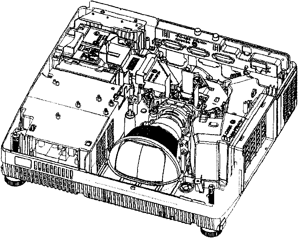
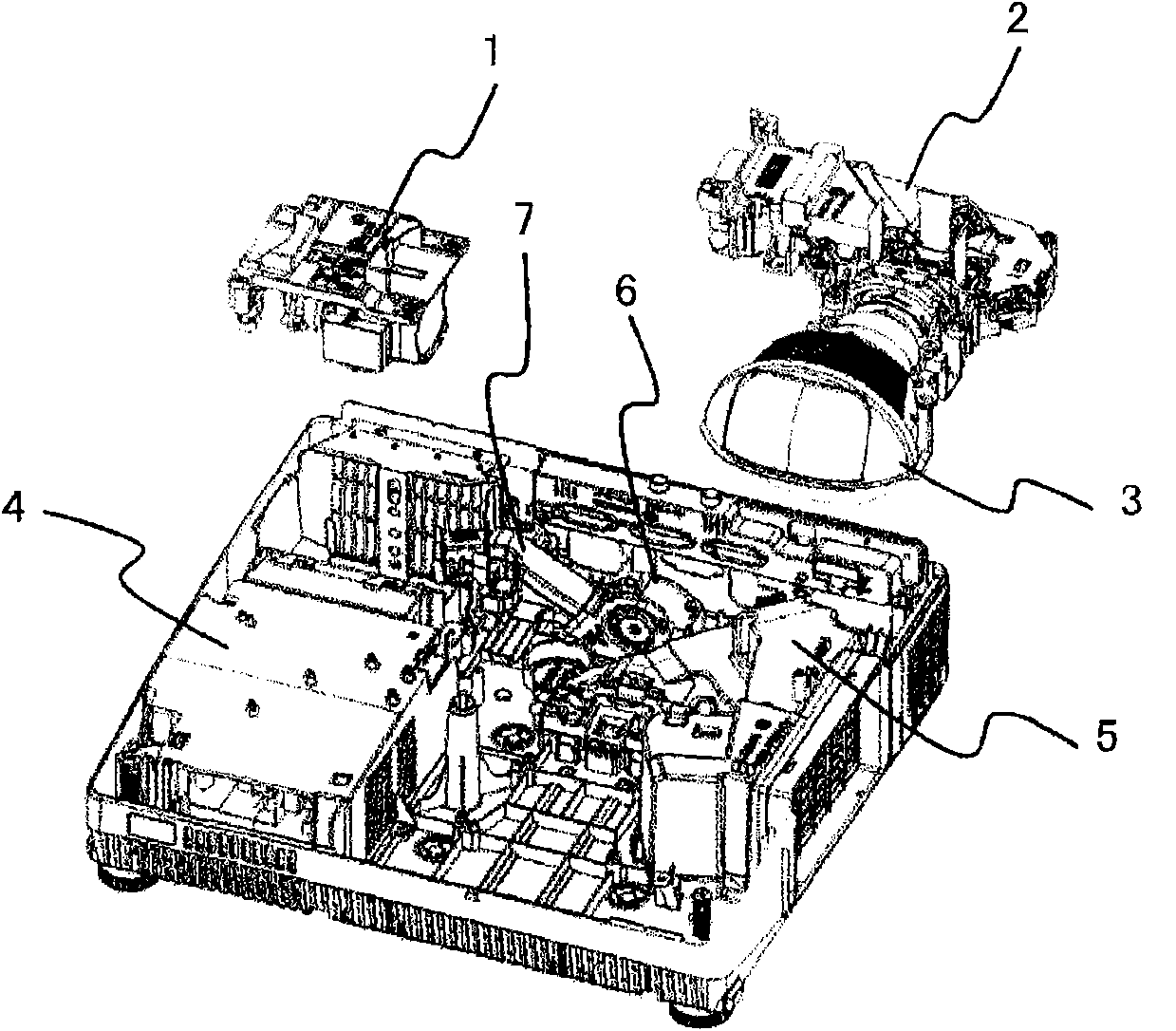
[0029] Figure 1a and Figure 1b It is an overall configuration diagram of the projection-type image display device of the present embodiment and a diagram showing how each configuration unit is separated from the overall configuration diagram.
[0030] The projection image display device of this embodiment includes: a lamp unit 1 including a light source, an optical engine 2 for generating images, a projection lens 3 for projecting images, a power supply unit 4, a panel channel 5, a cooling fan 6, a lamp channel 7, and the like.
[0031] Here, discharge lamps such as high-pressure mercury lamps are often used as light sources of projection-type image display devices. ...
Embodiment 2
[0079] In Embodiment 1, a projection type image display device including the movable rectifying plate 17 is described. That is, the movable rectifying plate 17 rotates around the support shaft by its own weight in order to increase The moment generated by gravity uses a material with a high specific gravity.
[0080] In this embodiment, an example will be described in which, as in the first embodiment, the moment is not increased by simply increasing the specific gravity of the material for the movable rectifying plate that rotates around the support shaft by its own weight.
[0081] In addition, in the projection-type image display device of this embodiment, the movable rectifying plate 17 in Embodiment 1 is replaced by the movable rectifying plate of this embodiment, and other structures and actions are the same as those of the projection-type image display device of Embodiment 1. The structure and operation of the display device are the same, so descriptions other than the ...
Embodiment 3
[0091] In Embodiment 1 and Embodiment 2, the projection type image display device including the movable rectifying plate 17 that rotates by its own weight around the support shaft 16 is described.
[0092] In this embodiment, a projection type image display device including a movable rectifying plate 20 that slides in the direction of gravity by its own weight will be described.
[0093] In addition, in the projection-type image display device of this embodiment, the movable rectifying plate 17 of the first embodiment is replaced with the movable rectifying plate 20, and other structures and operations are the same as those of the projection-type image display device of the first embodiment. , and the operation are the same, and therefore descriptions other than the movable rectifying plate 20 are omitted.
[0094] FIG. 9 shows a cross-sectional structure of the projection type image display device of this embodiment.
[0095] As described in Embodiment 1, the cooling air out...
PUM
 Abstract
Description
Claims
Application Information
 - R&D
- Intellectual Property
- Life Sciences
- Materials
- Tech Scout
- Unparalleled Data Quality
- Higher Quality Content
- 60% Fewer Hallucinations
Browse by: Latest US Patents, China's latest patents, Technical Efficacy Thesaurus, Application Domain, Technology Topic, Popular Technical Reports.
© 2025 PatSnap. All rights reserved.Legal|Privacy policy|Modern Slavery Act Transparency Statement|Sitemap|About US| Contact US: help@patsnap.com


