
Jointed spearhead assembly

A connected and spearhead technology, applied in the field of spearhead assembly, can solve problems such as deformation, tripping, failure, and weakness

Inactive Publication Date: 2014-11-05
LONGYEAR TM
View PDF6 Cites 0 Cited by
  • Summary
  • Abstract
  • Description
  • Claims
  • Application Information

AI Technical Summary

Problems solved by technology

However, the design of these attached drills can add various limitations, for example, causing the spearhead to be weak near the rotational attachment point
Therefore, when these connections are abused or overloaded, they can deform, unintentionally trip or fail

Method used


Image

  • Jointed spearhead assembly
  • Jointed spearhead assembly
  • Jointed spearhead assembly

Examples


Embodiment Construction

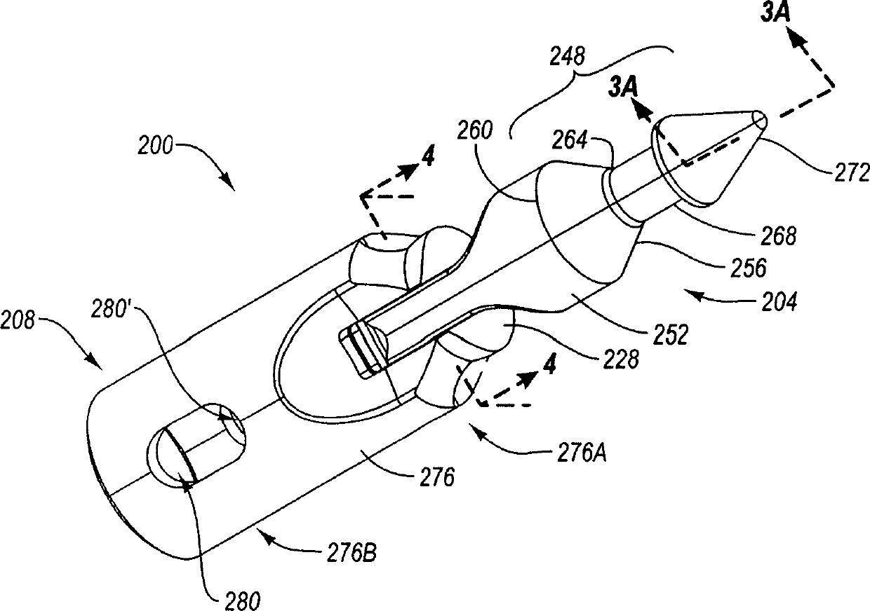
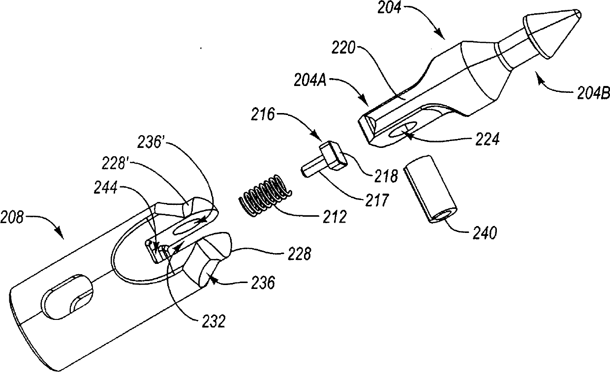
[0021] Herein, a spearhead assembly, method and system are provided. The spearhead assembly includes a spearhead and a base. The spearhead may have a follower tab having a non-convex first surface. A follower and biasing element are connected to the base so as to be located at least partially within the base.

[0022] Such a configuration may allow the spearhead assembly to be rotatably connected to help transfer mechanical stress and strain from the weakest point to an area of ​​greater strength and durability. Furthermore, since the loading element can be placed in a recess in the base, safety is increased since the operator cannot be caught or otherwise injured by the exposed spring of the loading element. Additionally, the loading element may be located on the outside of the follower, inside the base, as opposed to inside the follower tab. Such a configuration may allow the loading element to be larger and stronger than conventional springs.

[0023] In addition, the s...


PUM


Abstract

A jointed spearhead assembly can include a base portion that is adapted to be connected to a down-hole object and a spearhead portion having a first end and a second. The second end includes a follower tab with a non-convex first follower interface. The spearhead portion can be pivotally coupled to the base portion.

Description

technical field [0001] The present application relates to a spearhead assembly for underground drilling. Background technique [0002] During some drilling operations, wireline and cable cars are used to lower and retrieve various tools or other downhole equipment into and out of the borehole. For example, a wireline can be attached to the upper portion of an overshot, and then the spearhead assembly attached to the core remover can be lowered or retracted. When retrieving these devices, wirelines and cable cars typically lift the corer until it is fully pulled out of the borehole. At this point, the lower end of the core remover will be removed from the borehole and then lowered to lie flat on the ground. As the connected overshot, spearhead and corer assembly is lowered, high loads are exerted on the various components and cause deformation and failure of those components. [0003] In order to reduce the danger and damage associated with moving these linkages, some dril...

Claims


Application Information

Patent Timeline
Patent Type & Authority Patents(China)
IPC IPC(8): E21B23/14E21B25/02E21B25/14
CPCE21B31/18E21B17/023E21B25/00
Inventor 克里斯托弗·L·德伦特乔治·易布拉欣安东尼·拉钱斯
Owner LONGYEAR TM
Learn More