
Hydraulic system for sideboom

A hydraulic system and pipelayer technology, applied in the field of hydraulic systems, can solve problems such as immature controllers, low power utilization, and poor accuracy of compound actions, so as to avoid low power utilization, high power utilization, The effect of high movement precision

Inactive Publication Date: 2013-03-13
LIUZHOU HONGDA MACHINERY MFG
View PDF0 Cites 0 Cited by
  • Summary
  • Abstract
  • Description
  • Claims
  • Application Information

AI Technical Summary

Problems solved by technology

The first type of pipelayer was redeveloped on the basis of the bulldozer. Although its walking inherited the characteristics of fast speed of the bulldozer, it could not overcome the mechanical transmission characteristics such as smooth walking and poor operating comfort. In addition, due to the excessively prominent The secondary parameter is the walking speed, so that it has to be realized by increasing the engine power; for the second type of pipelayer that uses a closed hydraulic system to drive the walking, since the controller for constant power adjustment of the closed hydraulic system is not yet mature, At present, the form of simply limiting the maximum pressure is mainly adopted, so that the engine power cannot be fully utilized, and only a more powerful engine can be used. In addition, this type of pipelayer needs two independent hydraulic pumps to drive travel plus a working pump. , which requires at least 3 hydraulic pumps and a transfer case for driving multiple pumps, which greatly increases the matching cost of the pipelayer; The hydraulic system is used to drive the work, which has the disadvantages of low power utilization and poor precision of compound actions.

Method used


Image

  • Hydraulic system for sideboom
  • Hydraulic system for sideboom
  • Hydraulic system for sideboom

Examples


Embodiment

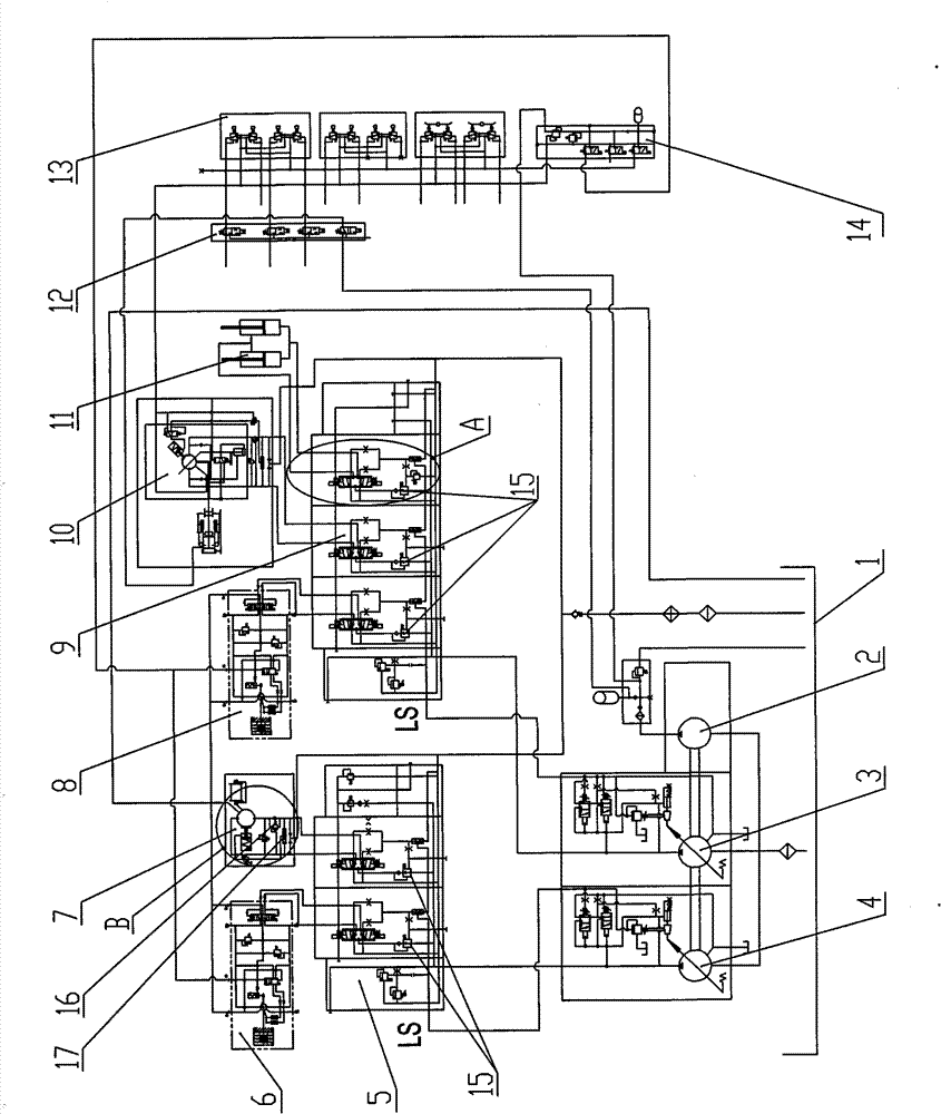
[0021] A hydraulic system for a pipelayer, which is a load sensitive hydraulic system such as figure 1 As shown, the load sensing hydraulic system includes two working pumps: working pump I (3) and working pump II (4), and two multi-way directional valves: multi-way directional valve I (5) and multi-way directional valve Directional valve II (9), and two travel motors: left travel motor 6 and right travel motor 8, working pump I (3), working pump II (4) and pilot pump (2) are triple pumps connected to oil tank 1 To supply oil to the system, pilot pump 2, which is in charge of pilot control and emergency hook throwing, is connected to pilot valve 13 and solenoid valve group II (14) respectively, and working pump I (3) is respectively It is connected with the right traveling motor 8, the hoisting winch 10 and the oil cylinder 11, and the working pump II (4) is connected with the left traveling motor 6 and the luffing hoist 7 through the multi-way reversing valve I (5); the left ...


PUM


Abstract

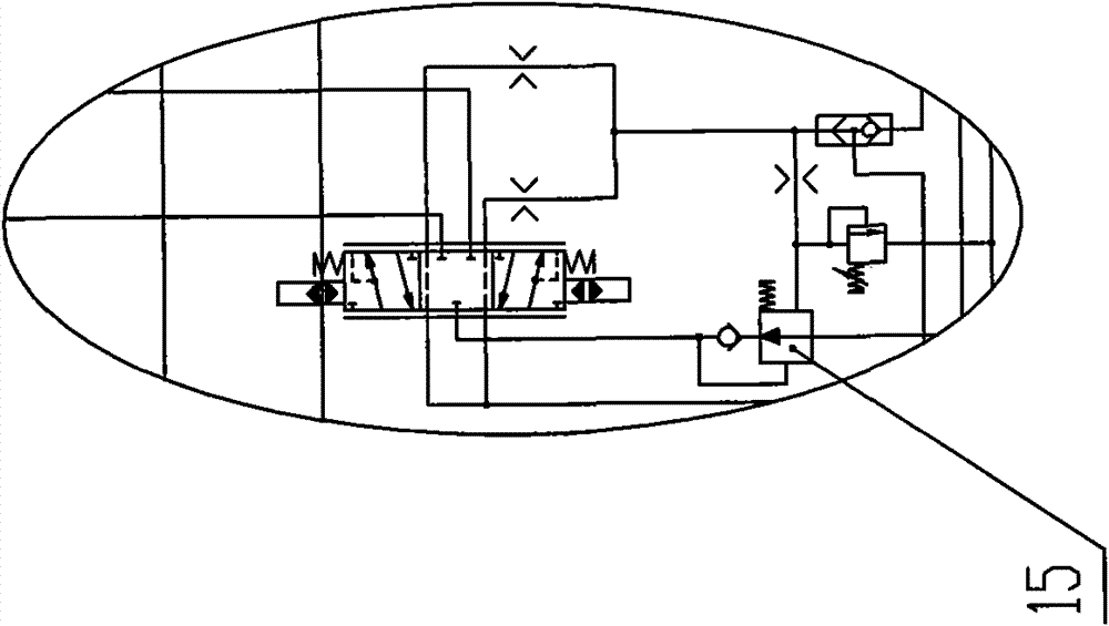
The invention relates to a hydraulic system for a sideboom, which is a load sensitive hydraulic system. The system comprises two working pumps I and II, two multiple directional control valves I and II and two traveling motors, namely a left traveling motor and a right traveling motor, wherein the working pump I, the working pump II and a pilot pump are a triple pump and are connected with an oil tank; the pilot pump is connected with a pilot valve and a solenoid valve bank I respectively; the working pump I is connected with the right traveling motor, a hoisting winch and an oil cylinder through the multiple directional control valve II respectively; the working pump II is connected with the left traveling motor and an amplitude-change winch through the multiple directional control valve I; the left traveling motor and the right traveling motor are connected mutually and are connected with a solenoid valve bank II; and a pressure compensation valve is arranged on each valve plate on the two multiple directional control valves. The sideboom with the hydraulic system has high action accuracy, excellent working performance, high utilization rate of engine power, low cost and operation comfort.

Description

【Technical field】 [0001] The invention relates to a hydraulic system of a pipelayer. 【Background technique】 [0002] At present, there are mainly two types of pipelayers at home and abroad: one is secondary development on the basis of bulldozers, which adopts mechanical transmission to drive walking and open quantitative hydraulic system to drive work; the other uses closed hydraulic The system drives the walking, and the open quantitative hydraulic system drives the work. The first type of pipelayer was redeveloped on the basis of the bulldozer. Although its walking inherited the characteristics of fast speed of the bulldozer, it could not overcome the mechanical transmission characteristics such as smooth walking and poor operating comfort. In addition, due to the excessively prominent The secondary parameter is the walking speed, so that it has to be realized by increasing the engine power; for the second type of pipelayer that uses a closed hydraulic system to drive the...

Claims


Application Information

Patent Timeline
Patent Type & Authority Patents(China)
IPC IPC(8): B66D1/08B66C23/62B66C23/88
Inventor 欧强莫国强彭兵杨星任
Owner LIUZHOU HONGDA MACHINERY MFG
Learn More