
Manufacture method of metal composite board

A technology of metal composite panels and manufacturing methods, applied in the direction of metal layered products, chemical instruments and methods, lamination, etc., can solve the problems of low efficiency, low composite strength, and inability to produce composite strength, etc. The effect of less deformation and high yield

Inactive Publication Date: 2011-03-30
SICHUAN MCWELL TECH
View PDF1 Cites 6 Cited by
  • Summary
  • Abstract
  • Description
  • Claims
  • Application Information

AI Technical Summary

Problems solved by technology

[0002] The existing cold rolling method to produce metal clad plates is usually after the surface of the metal to be clad is cleaned, then polished to make the surface rough, and then cold rolled to extrude the two plates. Due to the strong extrusion force, the metal contact surface Deformation and produce a wide gap, the two metals enter the gap with each other, continue to apply strong pressure, so that the plate continues to deform, the two metals can form an inlay with each other or meet with fresh metal below the joint surface to form a bond, so that the metal plate can be realized. Preliminary composite, after diffusion annealing to form a strong composite strength, this production process is very inefficient when realizing the preliminary composite of the plate, generally within 10 meters per minute, and the composite strength of this metal composite plate is low, especially For the composite of stainless steel and carbon steel, due to the high plasticity of stainless steel, it is not easy to produce wide cracks, and it is not easy to produce inlays between plates. Even if the deformation is about 50%, it can be separated by hand after initial compounding. When the composite speed is high, the initial composite strength will be lower, and the required composite strength cannot be produced

Method used


Image

  • Manufacture method of metal composite board
  • Manufacture method of metal composite board
  • Manufacture method of metal composite board

Examples


Embodiment Construction

[0015] The present invention will be further described below in conjunction with the accompanying drawings and embodiments.

[0016] see Figure 1 to Figure 4 , a method for manufacturing a metal composite panel, comprising the steps of:

[0017] (1) cleaning the composite surface of the base layer blank 1 and the multilayer blank 2 to remove surface impurities;

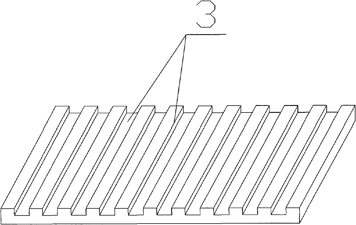
[0018] (2) On the composite surface of the base blank 1, the concave-convex lines 3 or the concave-convex blocks 4 are pressed with a mold, and the concave-convex lines 3 on the composite surface of the base blank 1 are also made with a mold on the composite surface of the base blank 1 Or concave-convex block 4 matching concave-convex line 3 or concave-convex block 4. As a preference, the composite surface of this embodiment is preferably made with concave-convex lines 3 , and the mold can be a concave-convex mold capable of producing concave-convex lines 3 .

[0019] (3) The base layer blank 1 and the multi-layer...


PUM


Abstract

The invention discloses a manufacture method of a metal composite board, and relates to a manufacture process of the composite board, which comprises the following steps of: firstly, cleaning a composite surface of a base blank and a clad blank for removing surface impurities; secondly, manufacturing concave-convex lines or pressing concave-convex blocks on the composite surface of the base blank by using a die, making concave-convex lines or concave-convex blocks matched with the concave-convex lines or pressing concave-convex blocks on the composite surface of the base blank on the composite surface of the clad blank by using the die; and thirdly, mutually embedding and matching the base blank and the clad blank of the concave-convex lines or pressing concave-convex blocks together to be extruded to form a wedge structure which is not easy to separate so that the composite strength is higher. Meanwhile, compared with the traditional production process, the invention has the advantages of high production efficiency and high yield.

Description

technical field [0001] The invention relates to a manufacturing process of a composite board, in particular to a manufacturing method of a metal composite board. Background technique [0002] The existing cold rolling method to produce metal clad plates is usually after the surface of the metal to be clad is cleaned, then polished to make the surface rough, and then cold rolled to extrude the two plates. Due to the strong extrusion force, the metal contact surface Deformation and produce a wide gap, the two metals enter the gap with each other, continue to apply strong pressure, so that the plate continues to deform, the two metals can form an inlay with each other or meet with fresh metal below the joint surface to form a bond, so that the metal plate can be realized. Preliminary composite, after diffusion annealing to form a strong composite strength, this production process is very inefficient when realizing the preliminary composite of the plate, generally within 10 mete...

Claims


Application Information

Patent Timeline
Patent Type & Authority Applications(China)
IPC IPC(8): B32B15/01B32B15/18B32B37/10B32B38/06
Inventor 彭大林梁鹏
Owner SICHUAN MCWELL TECH
Learn More