Fluidzed carbon filter sieve

A filter sieve and fluidized carbon technology, applied in the direction of filtration separation, gravity filter, loose filter material filter, etc., can solve the problems of easy formation of anaerobic state, high labor intensity, short service life of carbon, etc., and achieve structural Simple and reasonable, reduce labor intensity, stable operation effect

Inactive Publication Date: 2011-03-30
黑龙江华耐环境工程技术开发有限公司
View PDF3 Cites 0 Cited by
  • Summary
  • Abstract
  • Description
  • Claims
  • Application Information

AI Technical Summary

Problems solved by technology

[0003] The purpose of the present invention is to solve the problems that the existing activated carbon deep purification technology adopts artificial carbon loading, high labor intensity, short service life of carbon and easy formation of anaerobic state inside, and further provides a fluidized carbon filter screen

Method used


Image

  • Fluidzed carbon filter sieve
  • Fluidzed carbon filter sieve
  • Fluidzed carbon filter sieve

Examples


specific Embodiment approach 1

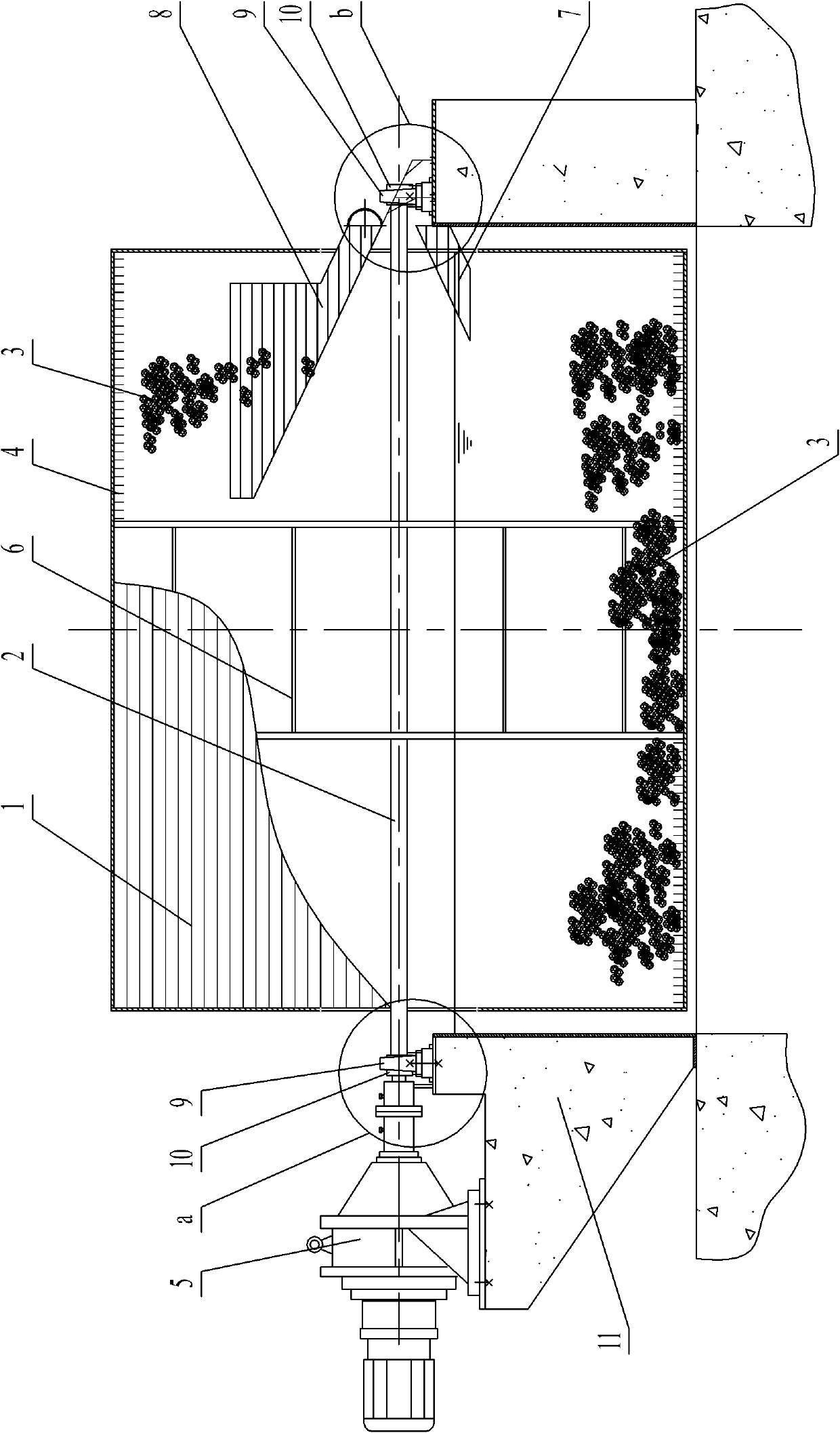
[0007] Specific implementation mode one: combine figure 1 , figure 2 , Figure 4 and Figure 5 To illustrate this embodiment, the fluidized carbon filter screen of this embodiment includes a grid type drum 1, a rotating shaft 2, an aeration discharge rake 4, a reduction motor 5, a drum support frame 6, a feed hopper 7, a discharge hopper 8, Two brackets 9, two bearings 10 and several spherical fillers 3, the deceleration motor 5 is fixedly installed on the water channel 11, the output end of the deceleration motor 5 is fixedly connected with one end of the rotating shaft 2, and the rotating shaft 2 is placed horizontally in the water channel 11, and both ends of the rotating shaft 2 are respectively connected to the water channel 11 through a bracket 9, a bearing 10 is provided between the rotating shaft 2 and the bracket 9, and the grid type roller 1 is set on the rotating shaft 2 and supported by the roller The frame 6 is fixedly connected with the rotating shaft 2, the ...

specific Embodiment approach 2

[0008] Specific implementation mode two: combination figure 1 The present embodiment will be described, and the geared motor 5 of the present embodiment is a stepless adjustment geared motor. Such setting realizes the stepless adjustment of the rotating speed of the grid-type drum during operation. Other compositions and connections are the same as in the first embodiment.

specific Embodiment approach 3

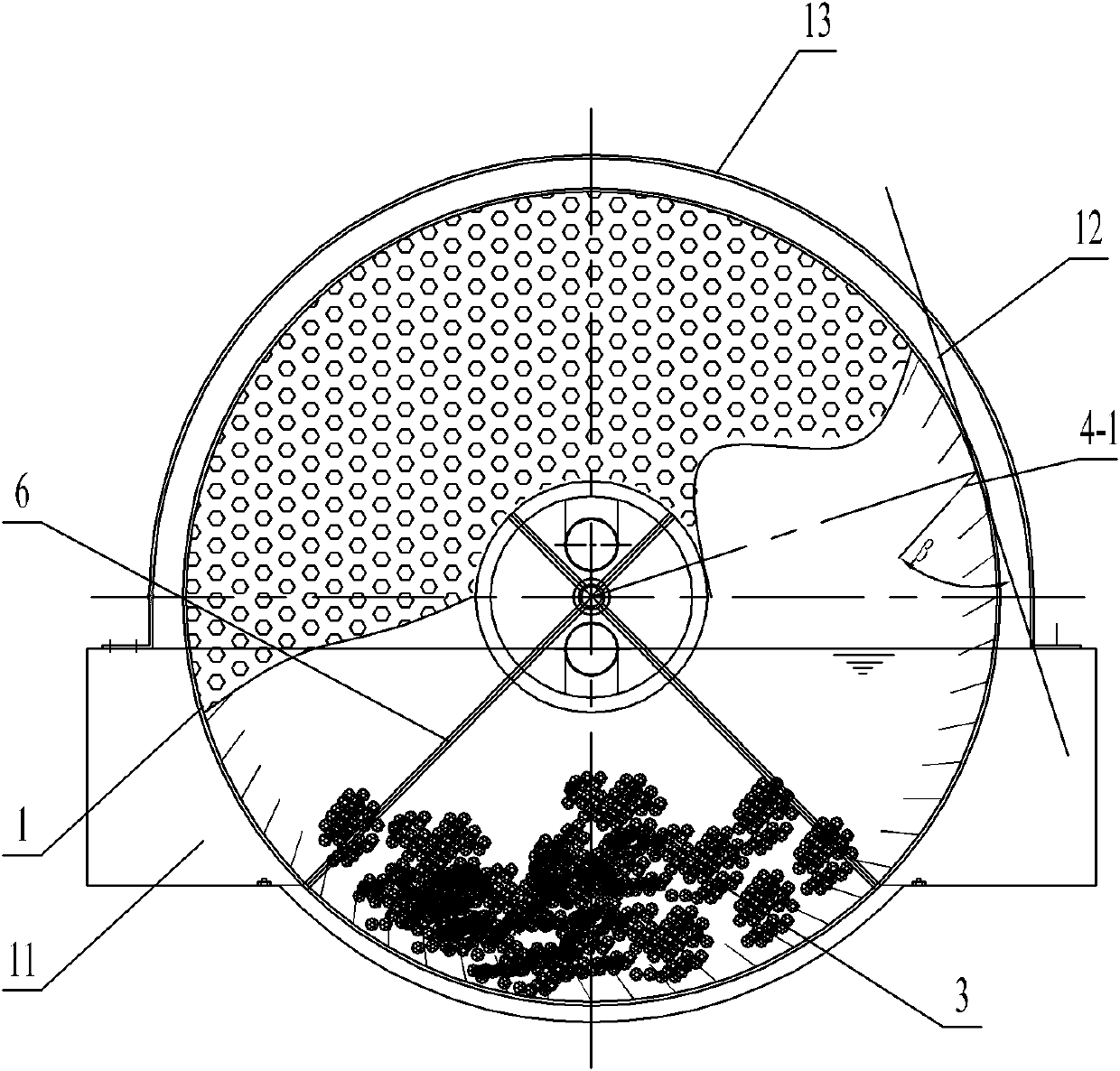
[0009] Specific implementation mode three: combination figure 2 To describe this embodiment, the acute angle β formed between the tangent line 12 of the connection point between each stainless steel bar 4-1 and the grid-type drum 1 and the stainless steel bar 4-1 in this embodiment is 60°. Such setting facilitates the flow of the spherical filler 3 from the grating drum 1 into the discharge hopper 8 under the action of centrifugal force. Other compositions and connections are the same as those in Embodiment 1 or Embodiment 2.


PUM


Abstract

The invention discloses a fluidized carbon filter sieve, relating to a filter sieve and solving the problems of large labor intensity, short service life of carbon and easy occurrence of interior anaerobic condition caused by manual carbon loading in the traditional deep purification technology of active carbon. In the invention, a deceleration motor is fixedly arranged on a ditch; the output endof the deceleration motor is fixedly connected with one end of a rotation shaft which is connected with the ditch through a bracket; a grille-type roller is sleeved on the rotation shaft and fixedly connected with the rotation shaft through a roller support frame; a plurality of spherical fillers are arranged in the grille-type roller; the inner wall of the grille-type roller is fixedly connectedwith an aeration discharging harrow; one end of a charging hopper is fixedly arranged on the ditch while the other end thereof passes through the side wall of the grille-type roller to be suspended in the grille-type roller; one end of a discharging hopper is arranged on the ditch while the other end thereof passes through the side wall of the grille-type roller to be suspended in the grille-typeroller; and the discharging hopper is located above the charging hopper. The fluidized carbon filter sieve is used for water purification.

Description

technical field [0001] The invention relates to a filter sieve, in particular to a fluidized carbon filter sieve, which belongs to the technical field of deep water purification. Background technique [0002] For a long time, the activated carbon depth filtration system of the waterworks has been using a fixed-bed filtration method, that is, the traditional method of fixing the activated carbon filter material in the filter tank is used for filtration, and the tap water flows under the pressure or gravity. The backwashing method and the fixed bed filtration method have an impact on the removal of micro-polluted organic matter and disinfection by-products in tap water. In the existing deep purification of tap water activated carbon, there is artificial loading of carbon, which is labor-intensive, has a short service life, and easily forms an anaerobic state inside, which is very unfavorable for deep purification of tap water. Contents of the invention [0003] The purpose ...

Claims


Application Information

Patent Timeline
Patent Type & Authority Applications(China)
IPC IPC(8): B01D24/36B01D24/46
Inventor 贾宇
Owner 黑龙江华耐环境工程技术开发有限公司
Why Eureka
Try Eureka