
Liquid crystal display device

A technology of liquid crystal display device and liquid crystal layer, applied in static indicators, nonlinear optics, optics, etc., can solve the problems of high brightness, poor light transmittance, serious color shift, etc.

Inactive Publication Date: 2011-03-23
INNOLUX CORP
View PDF4 Cites 8 Cited by
  • Summary
  • Abstract
  • Description
  • Claims
  • Application Information

AI Technical Summary

Problems solved by technology

[0004] However, in a twisted nematic liquid crystal display device, an alignment layer must be used to align the liquid crystal molecules above and below the liquid crystal layer, which makes the process time longer and the cost higher
In addition, the twisted nematic liquid crystal display device has disadvantages such as asymmetrical viewing angle, high brightness of the dark state picture, and low contrast ratio.
In the vertical alignment liquid crystal display device, there are disadvantages such as poor light transmittance, slow response speed and serious color shift.

Method used


Image

  • Liquid crystal display device
  • Liquid crystal display device
  • Liquid crystal display device

Examples


Embodiment Construction

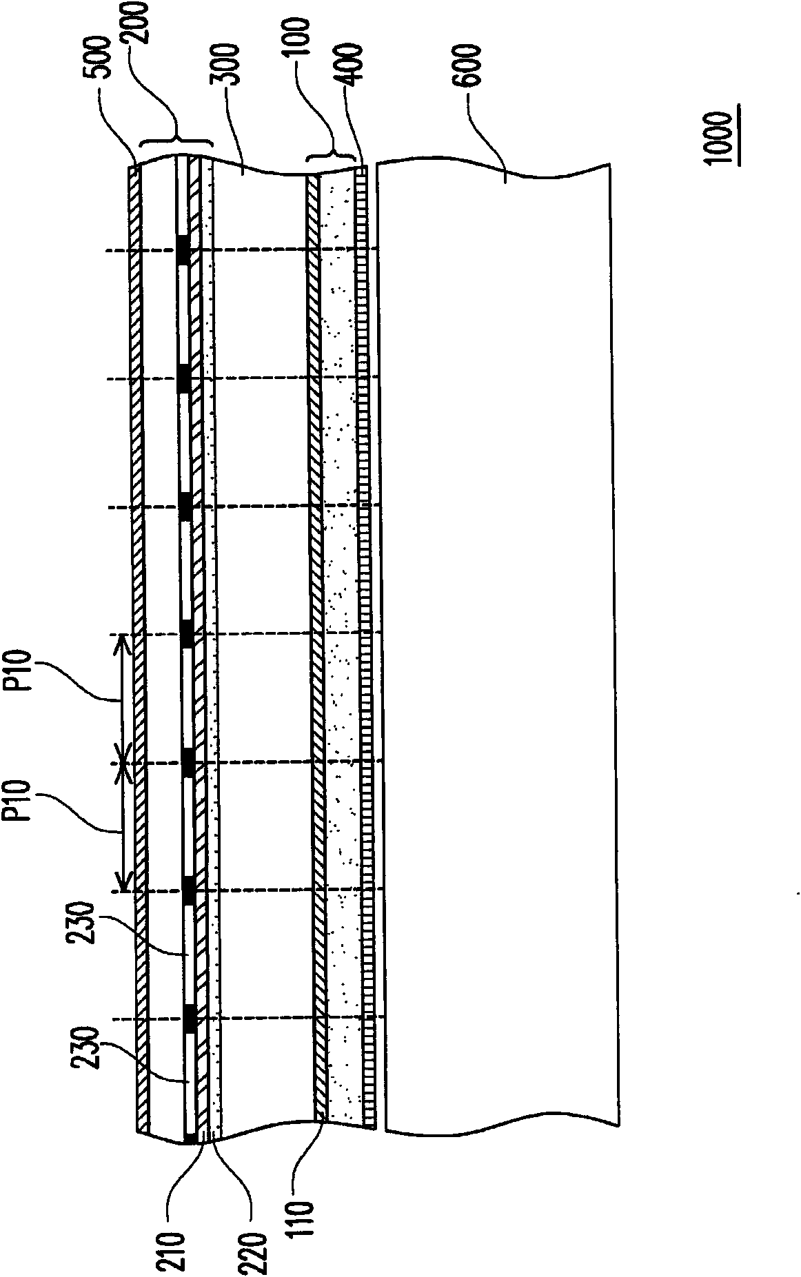
[0056] figure 1 It is a partial cross-sectional view of a liquid crystal display device according to an embodiment of the present invention. Please refer to figure 1 , the liquid crystal display device 1000 of this embodiment includes a first substrate 100 , a second substrate 200 and a liquid crystal layer 300 . The liquid crystal display device 1000 has at least one pixel area, and this embodiment is divided into a plurality of pixel areas P10 as an example. The liquid crystal layer 300 is disposed between the first substrate 100 and the second substrate 200 , and the first substrate 100 is substantially parallel to the second substrate 200 . The second substrate 200 has a common electrode 210 and an alignment layer 220 . Wherein, the alignment layer 220 covers the common electrode 210 , and the alignment layer 220 is close to the liquid crystal layer 300 .

[0057]In addition, the liquid crystal molecules of the liquid crystal layer 300 are, for example, negative type l...


PUM


Abstract

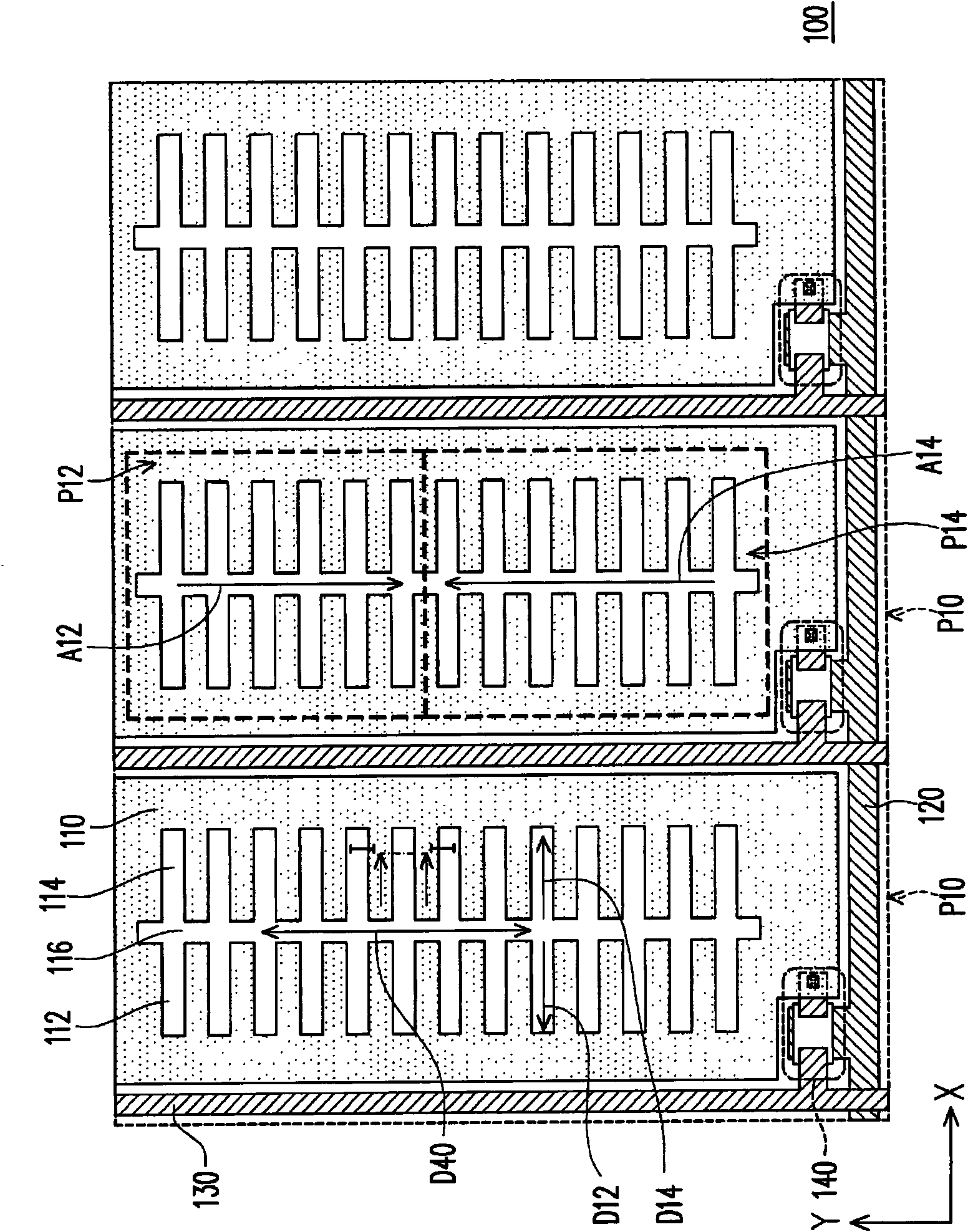
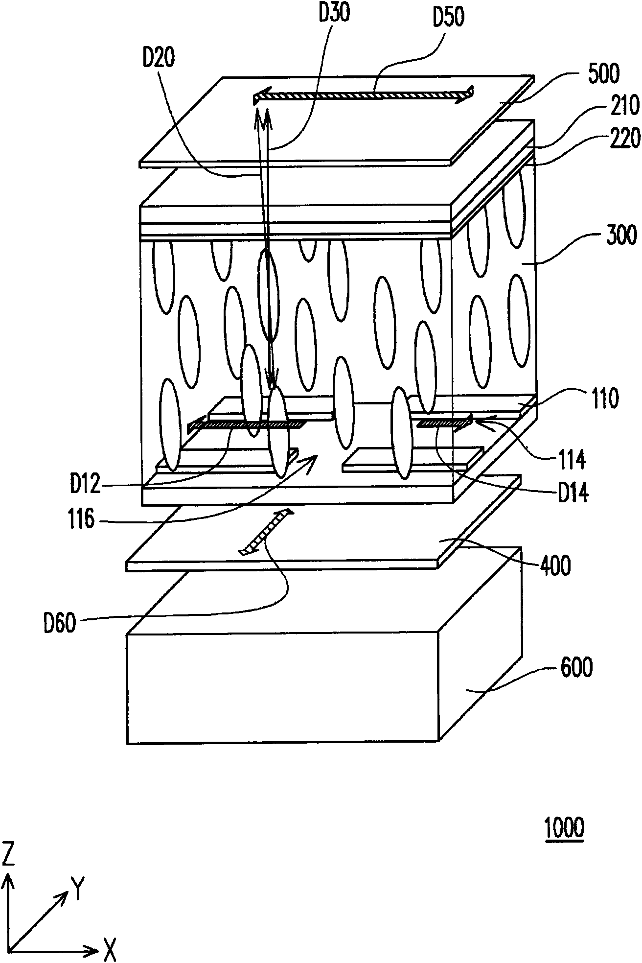
The invention discloses a liquid crystal display device, which comprises a first substrate, a second substrate and a liquid crystal layer. A pixel electrode of the first substrate comprises a plurality of first slits, a plurality of second slits and a third slit, wherein the first slits and the second slits are connected with the third slit; the first slits and the second slits respectively extend along a first vector and a second vector by taking connecting points with the third slit as starting points; the second substrate comprises a common electrode and an orientation layer which covers the common electrode; the liquid crystal layer is configured between the pixel electrode and the orientation layer; liquid crystal molecules of the liquid crystal layer close to the orientation layer are pre-inclined due to the orientation of the orientation layer; the projection of the long axes of at least partial pre-inclined liquid crystal molecules on the second substrate takes one end of each liquid crystal molecule close to the orientation layer as a starting point so as to form a third vector; an included angle between the third vector and the first vector is theta 1; and an included angle between the third vector and the second vector is theta 2, wherein the theta 1 is more than or equal to 90 degrees and less than or equal to 160 degrees, and the theta 2 is more than or equal to 90 degrees and less than or equal to 160 degrees. The transmittance and the visual angle symmetry can be improved.

Description

technical field [0001] The present invention relates to a display device, and in particular to a liquid crystal display. Background technique [0002] The rapid progress of the multimedia society is mostly due to the rapid progress of semiconductor devices or display devices. As far as display devices are concerned, liquid crystal display devices with superior characteristics such as high image quality, good space utilization efficiency, low power consumption, and no radiation have gradually become the mainstream of the market. [0003] At present, the performance requirements of the market for liquid crystal display devices are towards high contrast ratio, no gray scale inversion, low color shift, high luminance, high color Features such as richness, high color saturation, fast response and wide viewing angle. At present, the technologies that can meet the requirement of wide viewing angle include twisted nematic (TN) liquid crystal plus wide viewing film (wide viewing fi...

Claims


Application Information

Patent Timeline
IPC IPC(8): G02F1/133G02F1/1362
Inventor 王君瑞陈建宏谢志勇李恒贤许维婷
Owner INNOLUX CORP
Learn More