
Mechanical hand for stamping and automatic loading and unloading

A technology of manipulators and presses, which is applied in the field of metal pressure processing, can solve problems such as harsh working environment, inability to meet multiple varieties, modern production methods of small and medium batches, and difficulty in product adjustment, and achieve the effect of flexibility

Inactive Publication Date: 2011-03-23
孟津县平乐新兴铸造厂
View PDF0 Cites 46 Cited by
  • Summary
  • Abstract
  • Description
  • Claims
  • Application Information

AI Technical Summary

Problems solved by technology

[0002] Metal pressure processing technology is an extremely important processing method in machinery manufacturing, household appliances, instrumentation and other industries. Manual operation is completed, the production efficiency is low, the working environment is harsh, and personal injury accidents are unavoidable; in the existing automatic loading and unloading equipment for presses, the power output of the main shaft of the press is generally used as the drive or driven by a separate AC motor. Driven by connecting rod mechanism and other methods to realize the reciprocating motion in the horizontal and vertical directions required for loading and unloading
Its shortcomings are poor flexibility, difficult product adjustment, and cannot meet the requirements of modern production methods with multiple varieties and small and medium batches.

Method used


Image

  • Mechanical hand for stamping and automatic loading and unloading
  • Mechanical hand for stamping and automatic loading and unloading
  • Mechanical hand for stamping and automatic loading and unloading

Examples


Embodiment Construction

[0010] The structure and principle of the present invention will be described in further detail below in conjunction with the accompanying drawings.

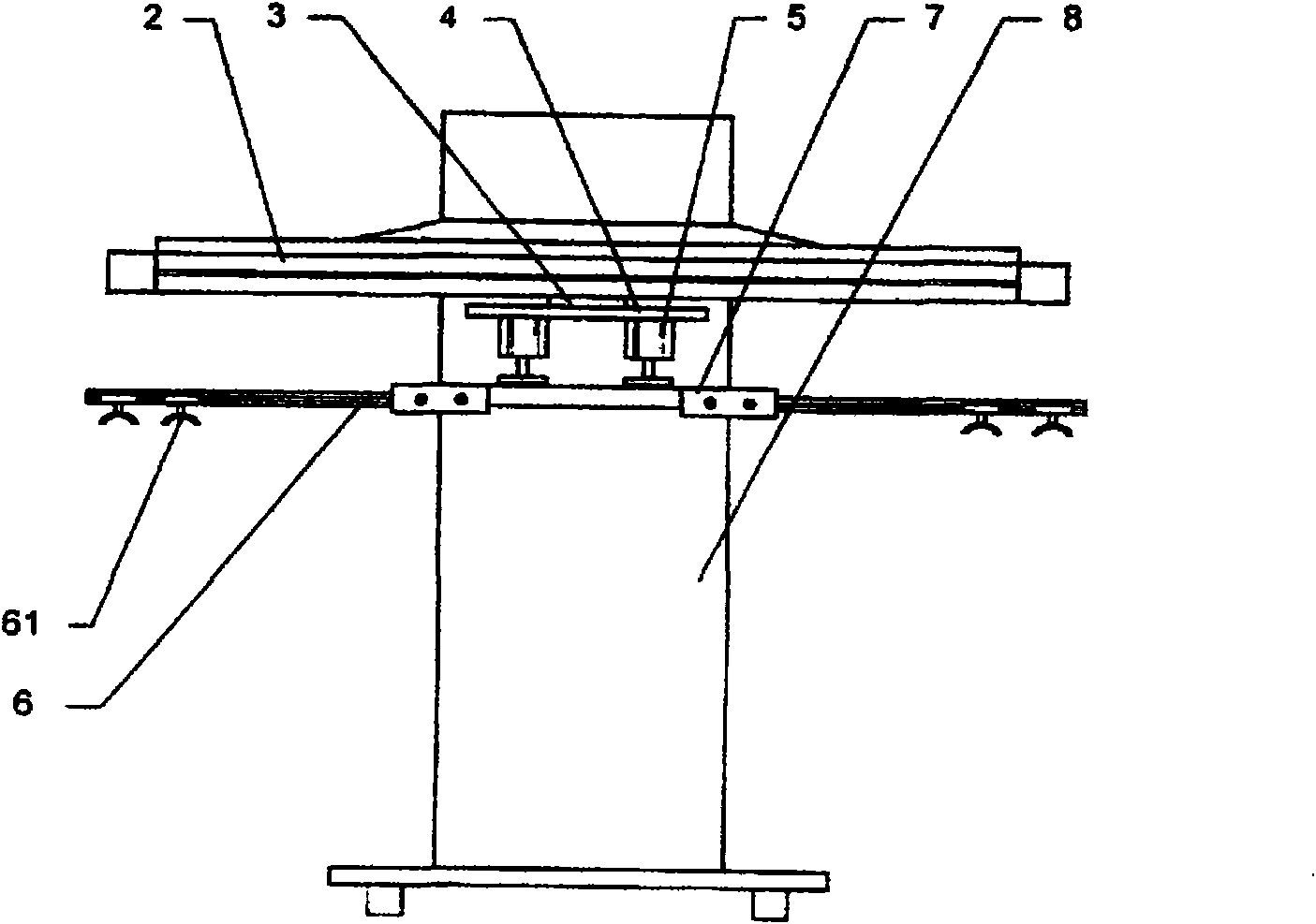
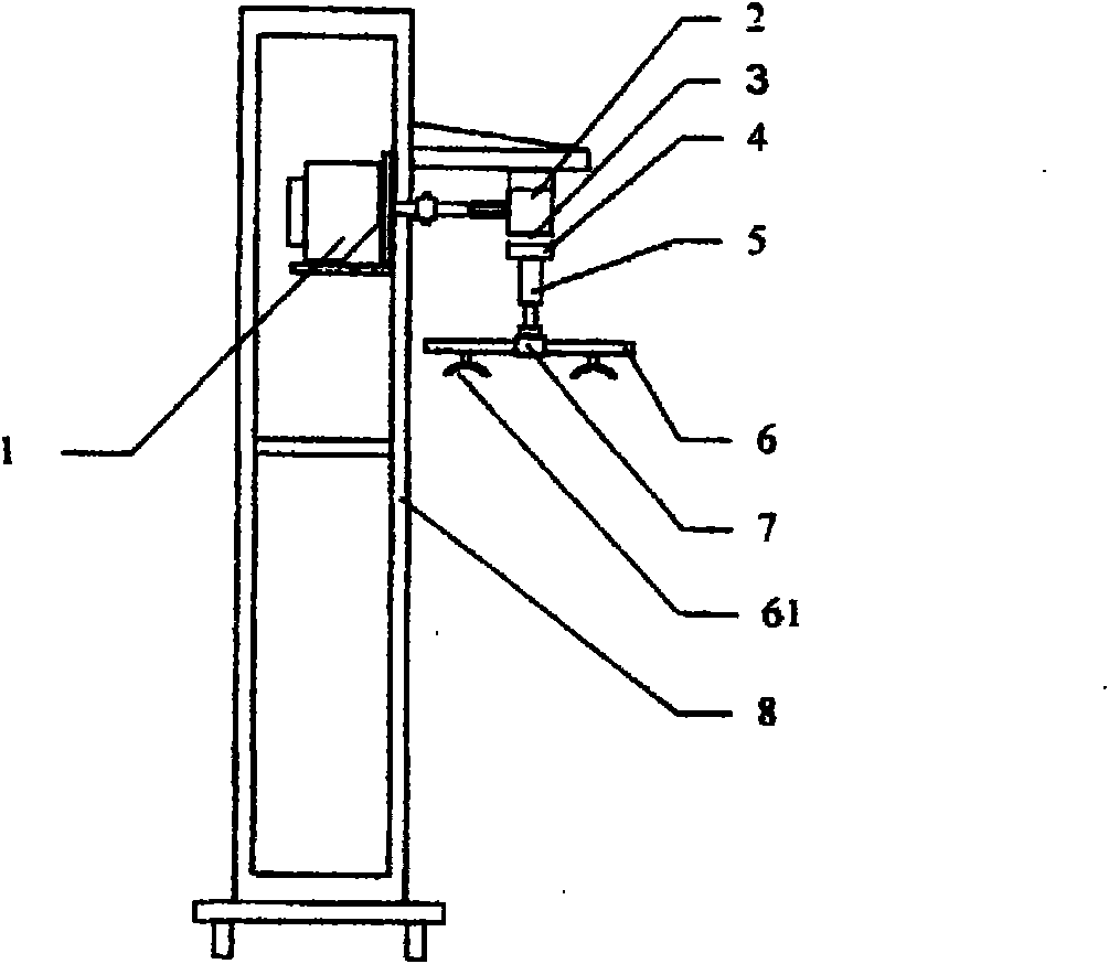
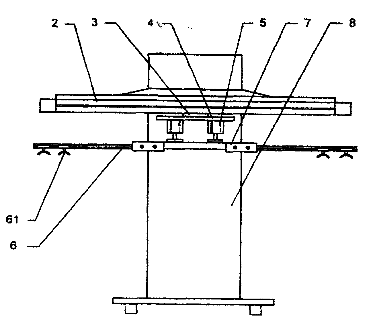
[0011] Such as figure 1 , 2 As shown, it is independently placed beside the press, including AC servo motor 1, linear guide rail 2, slider 3, cylinder 5, end picker 6, and frame 8, wherein the AC servo motor 1 controlled by the controller is installed on the frame 8, on one side of the frame 8, the AC servo motor 1 is meshed with the pulley of the linear guide rail 2 through a pulley of a synchronous belt, and the slider 3 is fixedly installed on the synchronous belt of the linear guide rail 2, and its sliding The bottom of the block 3 is fixedly connected with the cylinder 5 through the support plate 4, the support plate 7 is below the cylinder 5, and a detachable end picker 6 is provided on both sides of the support 7; the end picker 6 is provided with a mobile arm. The vacuum suction cup 61.

[0012] The controller connect...


PUM


Abstract

The invention discloses a mechanical hand for stamping and automatic loading and unloading, which is independently placed beside a press machine and comprises a servo motor (1), a linear guide rail (2), a sliding block (3), an air cylinder (5), end pickers (6) and a stand (8), wherein the servo motor (1) controlled by a controller is installed on the stand (8), and on one side of the stand (8), the servo motor (11) is engaged with a belt pulley of the linear guide rail (2) through a belt pulley of a synchronous belt; the sliding block (3) is fixedly installed on the synchronous belt of the linear guide rail (2), and the lower part of the sliding block (3) is fixedly connected with the air cylinder (5) through a support plate (4); a support seat (7) is located below the air cylinder (5), and the end pickers (6) are arranged on both sides of the support seat (7). Because the end pickers in the invention are removable, the position of a vacuum chuck is adjustable and the controller is in real-time control, the stamping production of different products and different press machines can be met, and the mechanical hand has flexibility.

Description

technical field [0001] The invention relates to metal pressure processing, in particular to a stamping automatic loading and unloading device suitable for automatic stamping production, especially suitable for high-speed and safe production of small and medium-sized open presses and forming an automatic stamping production line for production. Background technique [0002] Metal pressure processing technology is an extremely important processing method in machinery manufacturing, household appliances, instrumentation and other industries. Manual operation is completed, the production efficiency is low, the working environment is harsh, and personal injury accidents are unavoidable; in the existing automatic loading and unloading equipment for presses, the power output of the main shaft of the press is generally used as the drive or driven by a separate AC motor. The connecting rod mechanism and other methods are used to realize the reciprocating motion in the horizontal and ...

Claims


Application Information

Patent Timeline
Patent Type & Authority Applications(China)
IPC IPC(8): B21D45/10B30B15/30B30B15/32B25J9/00
Inventor 吕国良
Owner 孟津县平乐新兴铸造厂
Learn More