A ground replacement air supply device

An air supply device and air outlet technology, which is applied in the field of floor replacement air supply devices, can solve the problems of single form and function, simple structure and single function of the air supply outlet, and achieves convenient pipeline installation, convenient and flexible maintenance, and solves condensation problems. water effect

Active Publication Date: 2015-09-09
CHINA NORTHWEST ARCHITECTURE DESIGN & RES INST CO LTD
View PDF13 Cites 0 Cited by
  • Summary
  • Abstract
  • Description
  • Claims
  • Application Information

AI Technical Summary

Problems solved by technology

[0002] At present, in the traditional form of replacement air supply outlet in the field of ventilation and air conditioning, the wind speed and air supply direction of the air outlet are generally not adjustable, and the uniformity of the air supply air flow is usually adjusted by a fixed metal grid plate device; the structure of the air supply outlet is simple and functional. Single, only for summer air supply requirements
However, in practical applications, the air supply parameters are often different in different seasons (mainly winter and summer). If the air supply cannot be adjusted, it is difficult to achieve the expected effect of replacing the air supply; at the same time, due to the single form and function Some devices such as water collectors, indoor loudspeakers and evacuation displays with floor radiation design have to be set up and installed independently, which not only affects the beauty of the room but also increases the investment cost.

Method used


Image

  • A ground replacement air supply device
  • A ground replacement air supply device
  • A ground replacement air supply device

Examples


Embodiment Construction

[0021] The present invention will be described in further detail below in conjunction with the accompanying drawings.

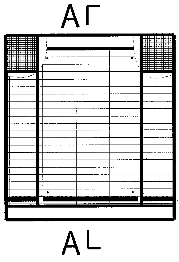
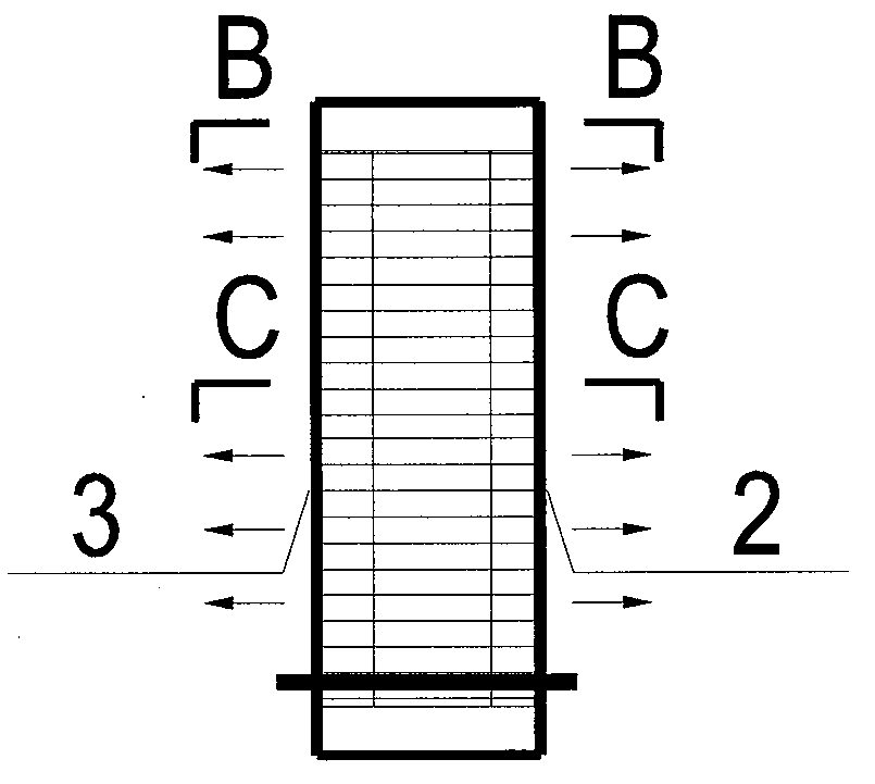
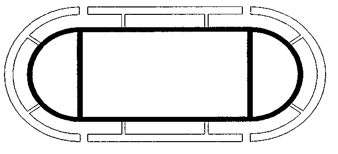
[0022] See Figure 1, figure 2 and image 3 , a floor replacement air supply device, including a roll-type cloth curtain 1 that can be pushed and pulled manually. The outer side of the roll-type cloth curtain 1 is the main air supply port 2 and the secondary air supply port 3. The middle part of the tuyere 3 is a conical cloth bag 4, and a sub-water collector 5 is arranged between the secondary air supply port 3 and the conical cloth bag 4. The top of the cloth bag 4 is fixed at the top center of the whole device, and the lower end is connected with the interface device 7. The interface device 7 is provided with an air volume valve 8, and a loudspeaker 9 and an evacuation indicating device instrument 10 are provided at the inner upper corner of the air supply device.

[0023] The roll-type cloth curtain 1 is fixed on the top of the whole device with a brack...


PUM


Abstract

The invention discloses a floor-type displacement air supply device comprising a drum-type windproof cloth curtain which can be manually pushed and pulled, wherein the outer side of the drum-type windproof cloth curtain is provided with a primary air supply outlet and a secondary air supply outlet, and the middle of the primary air supply outlet and the secondary air supply outlet is a ventilating current-sharing tapered cloth bag; a water knockout trap is arranged between the secondary air supply outlet and the tapered cloth bag; the outer surface of the water knockout trap is covered with a prefabricated integral thermal insulation shell; the top of the tapered cloth bag is fixed on the center of the top of the whole device, and the lower end of the tapered cloth bag is connected with an interface device; an air quantity valve for regulating and fixing is arranged in the interface device; and the upper angle of the air supply device is provided with a loudspeaker or an evacuation indicating device (instrument). The invention has the advantages that the air speed and direction of supplying air are easy to control, and the air distribution is even and can be regulated according to seasonal demands; in terms of the thermal insulation of the water knockout trap, the requirements of thermal isolation and no dew formation can be realized easily; and the pipeline construction and installation can be carried out conveniently. The integrated loudspeaker and the evacuation indicating device (instrument) can conveniently play roles in communicating, guiding and indicating indoor personnel.

Description

technical field [0001] The invention relates to the technical field of ventilation and air conditioning, in particular to a floor replacement air supply device. Background technique [0002] At present, in the traditional form of replacement air supply outlet in the field of ventilation and air conditioning, the wind speed and air supply direction of the air outlet are generally not adjustable, and the uniformity of the air supply air flow is usually adjusted by a fixed metal grid plate device; the structure of the air supply outlet is simple and functional. Single, only used for air supply requirements in summer. However, in practical applications, the air supply parameters are often different in different seasons (mainly winter and summer). If the air supply cannot be adjusted, it is difficult to achieve the expected effect of replacing the air supply; at the same time, due to the single form and function Some devices such as water collectors, indoor loudspeakers and evac...

Claims


Application Information

Patent Timeline
Patent Type & Authority Patents(China)
IPC IPC(8): F24F5/00F24F13/12F24F13/20F24F13/22
Inventor 周敏侯占魁
Owner CHINA NORTHWEST ARCHITECTURE DESIGN & RES INST CO LTD
Why Eureka
Try Eureka