Radar apparatus
A radar device and component technology, which is applied to measurement devices, radio wave reflection/re-radiation, utilization of re-radiation, etc. High angular accuracy and the effect of reducing side lobes
- Summary
- Abstract
- Description
- Claims
- Application Information
AI Technical Summary
Problems solved by technology
Method used
Image
Examples
Embodiment 1
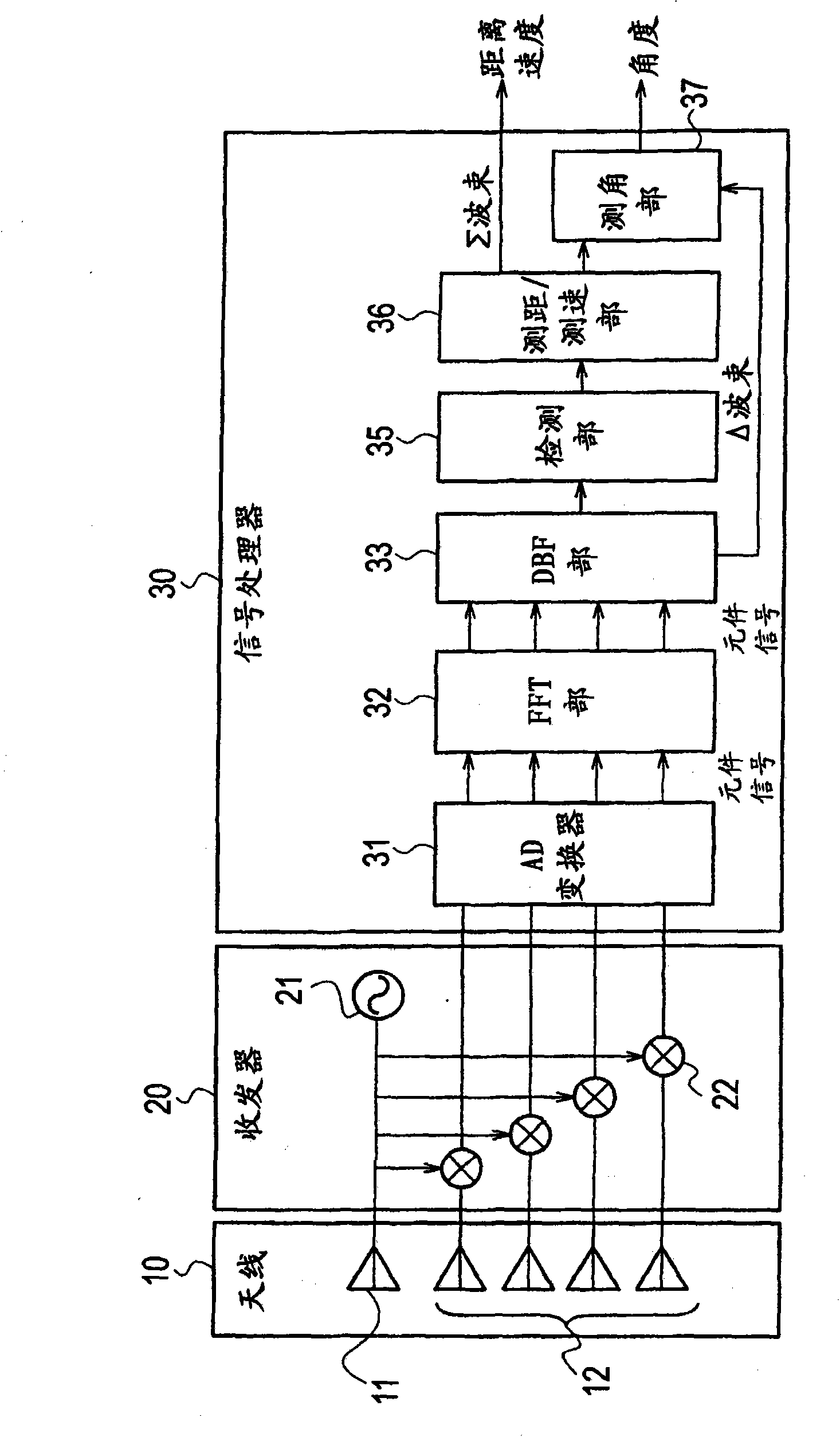
[0053] Figure 6 It is a system diagram showing the configuration of the radar device according to Embodiment 1 of the present invention. This radar device includes an antenna 10, a transceiver 20, and a signal processor 30a.
[0054] The antenna 10 is composed of an antenna radiating element 11 and a plurality of antenna receiving elements 12 . The antenna radiating element 11 converts a radiating signal transmitted from the transceiver 20 as an electric signal into an electric wave and sends it out to the outside. The plurality of antenna receiving elements 12 receive external radio waves, convert them into electrical signals, and send them to the transceiver 20 as received signals.
[0055] The transceiver 20 includes a transmitter 21 and a plurality of mixers 22 provided corresponding to the plurality of antenna receiving elements 12 . The transmitter 21 generates a transmission signal and sends it to the antenna radiating element 11 and a plurality of mixers 22 . The ...
Embodiment 2
[0115] Such as Figure 12 As shown in (a), when there are a plurality of reflection points in the same range in the detection Σ beam, if the angle measurement beam also includes a plurality of reflection points, the error of the angle measurement value may become large. As a countermeasure against this, the radar device according to Embodiment 2 of the present invention is such as Figure 12 (b), Figure 12 As shown in (c), the beam is shaped so that the angle measurement beam does not contain a plurality of reflection points, and the directing direction is changed. Figure 13 This shows the angle measurement range when the angle measurement beam (Σ beam, Σ2 beam) is formed.
[0116] Figure 8 It is a system diagram showing the configuration of the radar device according to the second embodiment of the present invention.
[0117] This radar device is configured by adding a beam forming unit 38 to the signal processor 30 a of the radar device according to the first embodime...
Embodiment 3
[0148] Figure 14 It is a system diagram showing the configuration of the radar device according to the third embodiment of the present invention. This radar device is configured by adding a correction circuit 39 to the signal processor 30b of the radar device according to the second embodiment. The correction circuit 39 calculates a correction coefficient based on the signal output from the FFT unit 32 and sends it to the DBF unit 33 .
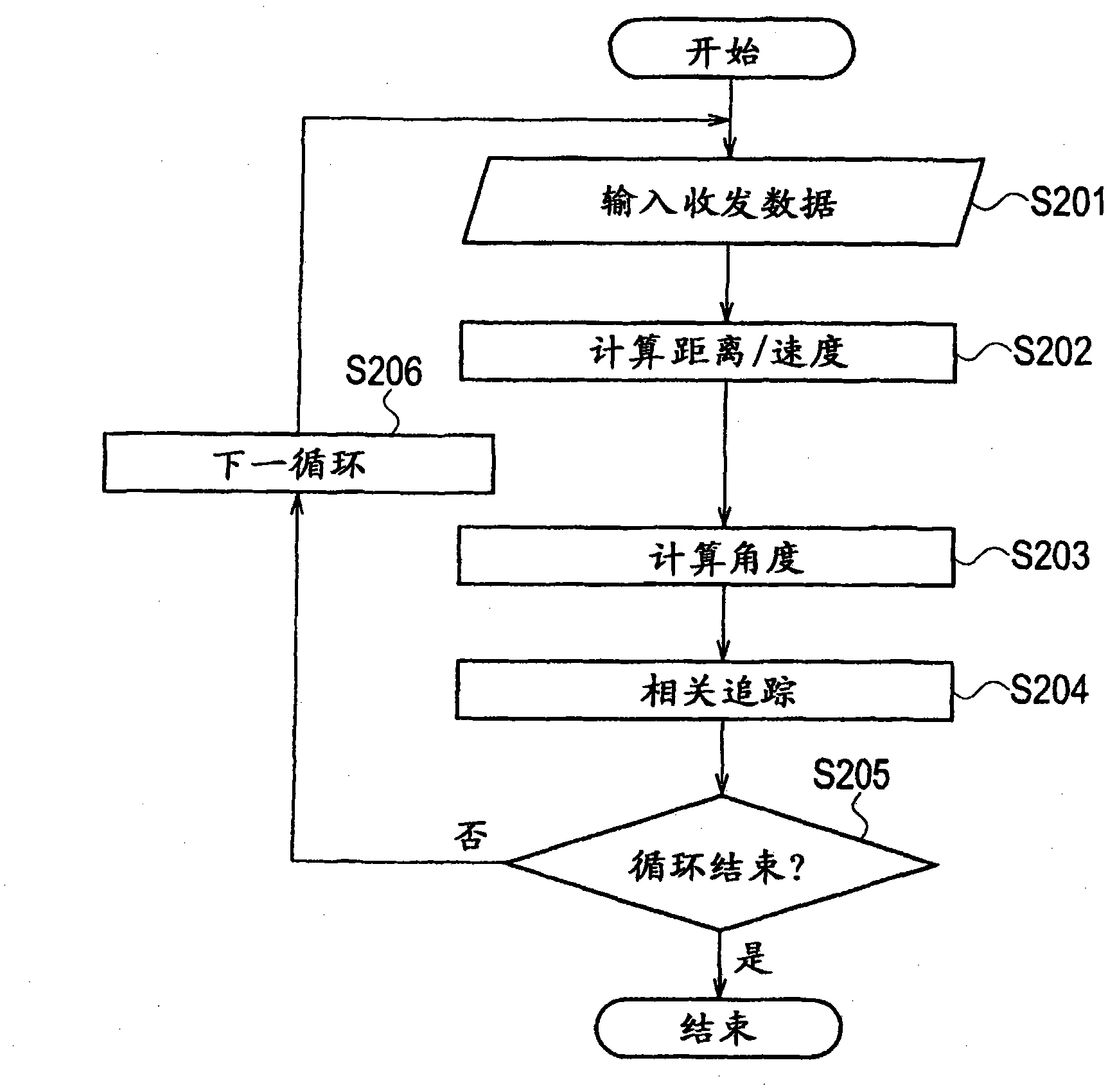
[0149] Figure 15 It is a flowchart showing the operation of the radar device according to the third embodiment of the present invention. The flow chart is in Figure 9 The shown flow chart showing the operation of the radar device according to the second embodiment is configured by adding a correction coefficient calculation process (step S31 ) between steps S11 and S12 . Next, the procedure for performing the same or equivalent processing as that of the radar device according to the above-mentioned embodiment 2 is added with Figure 9 ...
PUM
 Abstract
Description
Claims
Application Information
 - R&D Engineer
- R&D Manager
- IP Professional
- Industry Leading Data Capabilities
- Powerful AI technology
- Patent DNA Extraction
Browse by: Latest US Patents, China's latest patents, Technical Efficacy Thesaurus, Application Domain, Technology Topic, Popular Technical Reports.
© 2024 PatSnap. All rights reserved.Legal|Privacy policy|Modern Slavery Act Transparency Statement|Sitemap|About US| Contact US: help@patsnap.com


