Small electromechanical transducer, in particular a timepiece generator

A sensor and electromechanical technology, applied in electromechanical devices, electric winding, electric mechanical clocks, etc., can solve problems such as troublesome and complicated manufacturing, and achieve the effect of reducing costs and increasing duration

Active Publication Date: 2011-02-23
ETA SA MFG HORLOGERE SUISSE
View PDF6 Cites 0 Cited by
  • Summary
  • Abstract
  • Description
  • Claims
  • Application Information

AI Technical Summary

Problems solved by technology

However, this generator has several major disadvantages
First, it's relatively complex and troublesome

Method used


Image

  • Small electromechanical transducer, in particular a timepiece generator
  • Small electromechanical transducer, in particular a timepiece generator
  • Small electromechanical transducer, in particular a timepiece generator

Examples


Embodiment Construction

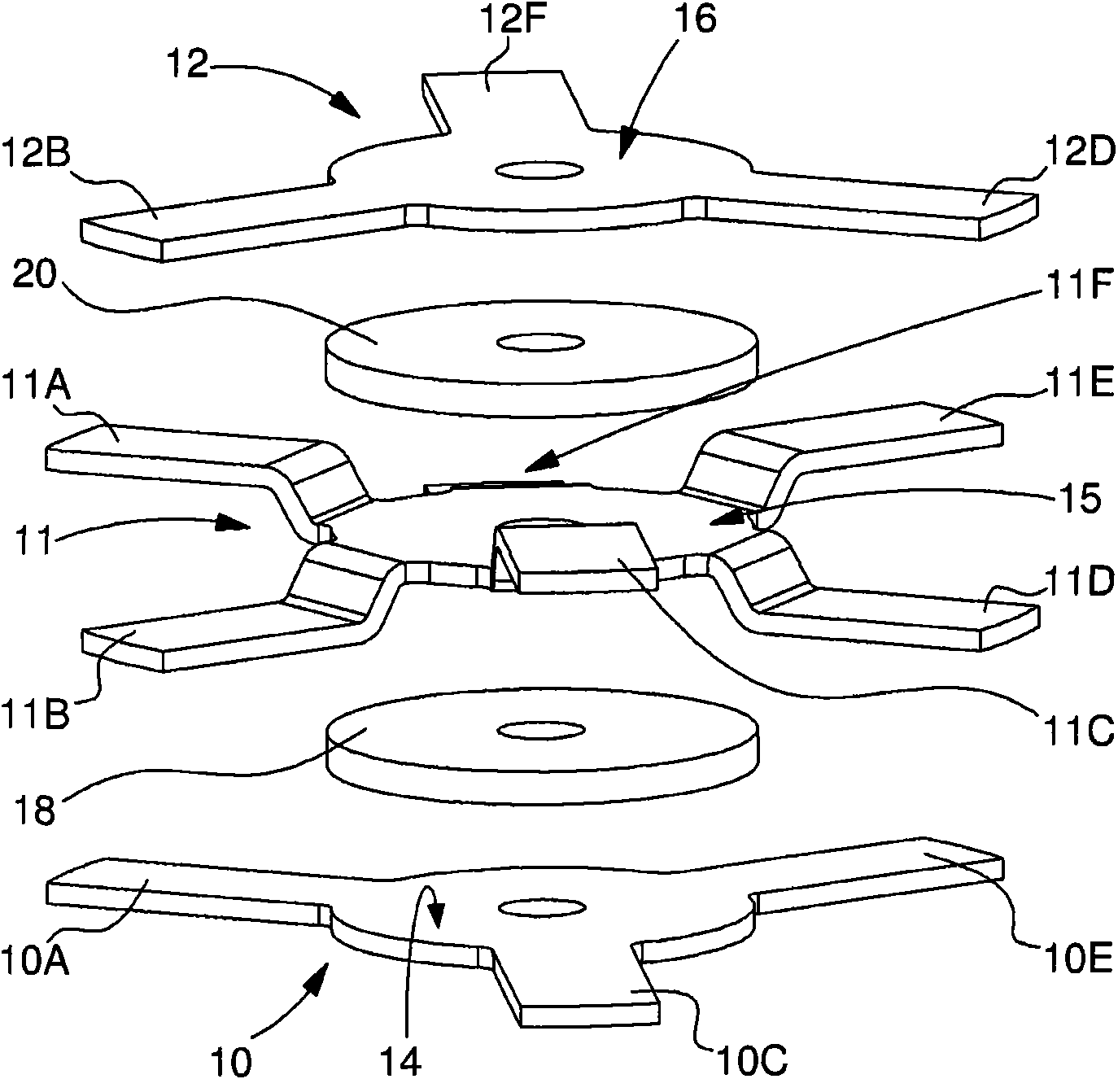
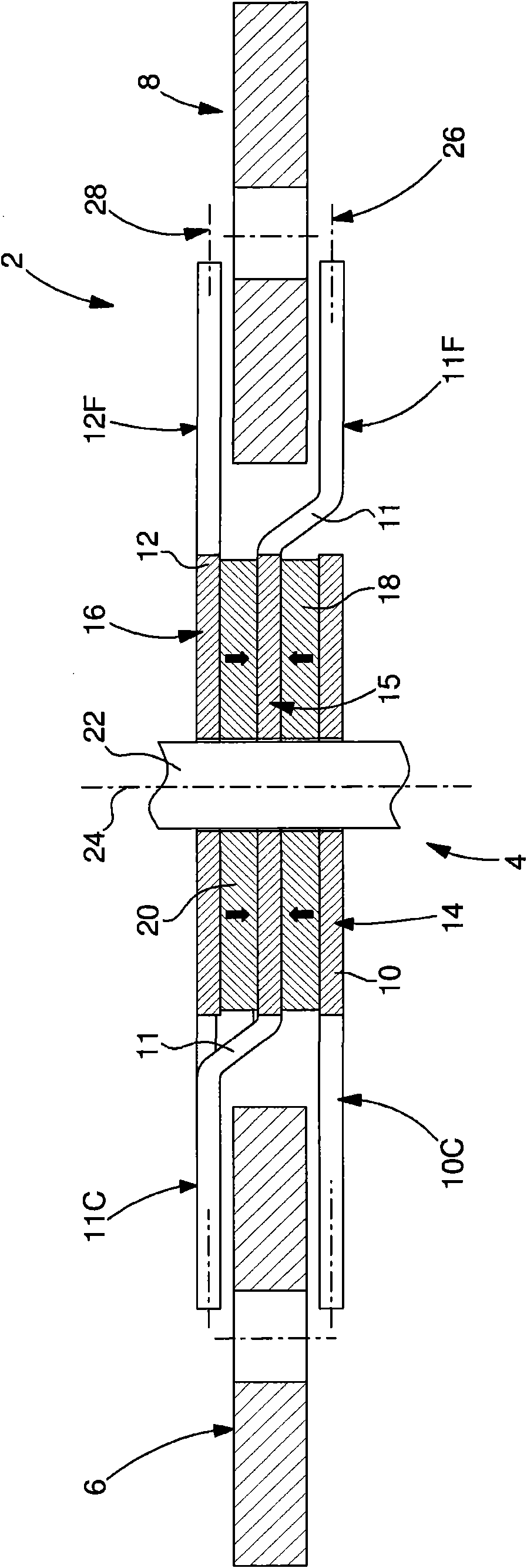
[0013] Refer to attached Figures 1 to 3 , in the following we will describe a preferred embodiment of a clock-type electromechanical sensor according to the present invention. In particular, the sensor forms a magnetoelectric generator 2 . The generator 2 comprises a rotor 4 and two planar coils 6 and 8 . It will be noted immediately that in the first variant only one coil 6 is provided; but in the second variant there are 3 coils, angularly deflected by 120°. The coils 6 and 8 have an angular deflection of 120° relative to the axis of rotation 20 of the rotor 4 .

[0014] The rotor 4 is formed by first, second and third parts 10, 11 and 12 made of magnetic material. The first magnetic portion 10 is formed by a planar structure defining a first central region 14 and three tongues 10A, 10C and 10E extending radially from the central region 14 . The three tongues are arranged in a uniform manner with an angular deflection of approximately 120°. The magnetic portion 10 thus...


PUM


Abstract

The invention relates to a smal electromechanical transducer, in particular a timepiece generator. The electromechanical transducer includes a rotor and two coil, the rotor being formed of first, second and third parts made of magnetic material with respectively first, second and third superposed central zones, a first, axially polarised, bipolar magnet being arranged between the first and secondcentral zones and a second bipolar magnet axially polarised in an opposite direction to that of the first magnet being arranged between the second and third central zones. The first and third parts each include N tongues, where N is a number greater than one (N>1), which extend radially from the central zone and the second part including 2N tongues, of which N first tongues are folded such that their respective end zones are arranged in a first geometrical plane (26) in which the tongues of said first part are located, and of which N second tongues are folded such that their respective end zones are arranged approximately in a second geometrical plane in which the tongues of said third part are located. The N first tongues of the second part are located respectively opposite the N tonguesof the third part whereas the N second tongues of said second part are located opposite the N tongues of the first part. The two coils are located between the first and second geometrical planes of the rotor such that, when the rotor is rotating, the end zones of the rotor tongues pass opposite said at least one coil.

Description

technical field [0001] The invention relates to an electromechanical sensor consisting of a rotor having a plurality of magnetic poles and at least one planar coil (relatively low in height) arranged so that when the rotor rotates, the magnetic poles of the rotor pass through all opposing said at least one coil. [0002] In particular, the electromechanical sensor defines a clock generator, ie a generator of small size or a magnetoelectric microgenerator. [0003] In particular, the clock generator according to the invention is used to incorporate a clock operation of the type disclosed in particular in EP Patent No. 239820 or 679968. Background technique [0004] A generator of the above-mentioned type with a multi-pole rotor is disclosed in German utility model DE 1811389 (U). This generator comprises a rotor consisting of a central shaft carrying two rims made of magnetic material, on the periphery of which are arranged permanent magnets of alternating polarity, six per...

Claims


Application Information

Patent Timeline
Patent Type & Authority Applications(China)
IPC IPC(8): H02K11/00
CPCG04C10/00H02K1/2793H02K21/24H02K1/2795
Inventor U·肖恩赫尔J·伯索德
Owner ETA SA MFG HORLOGERE SUISSE
Why Eureka
Try Eureka