Local exhaust apparatus

An exhaust system, local technology, applied in airflow control components, household heating, space heating and ventilation details, etc., can solve the problems of increasing the total number of local exhaust system components, high maintenance costs, and increased production costs.

Inactive Publication Date: 2011-02-09
GTEC
View PDF6 Cites 4 Cited by
  • Summary
  • Abstract
  • Description
  • Claims
  • Application Information

AI Technical Summary

Problems solved by technology

This becomes a factor of increasing the total amount of components of the local exhaust system, thereby increasing production costs, and gradually increasing power consumption per unit time, thereby easily making maintenance costs high

Method used


Image

  • Local exhaust apparatus
  • Local exhaust apparatus
  • Local exhaust apparatus

Examples


Embodiment Construction

[0040] Reference will now be made in detail to various embodiments of the invention, examples of which are illustrated in the accompanying drawings and the description below.

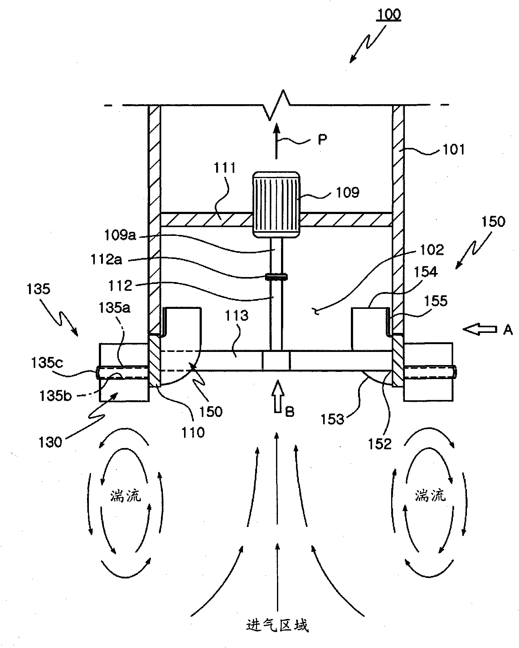
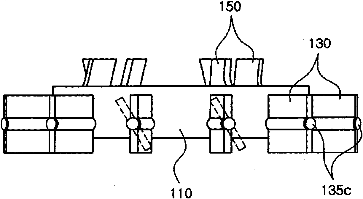
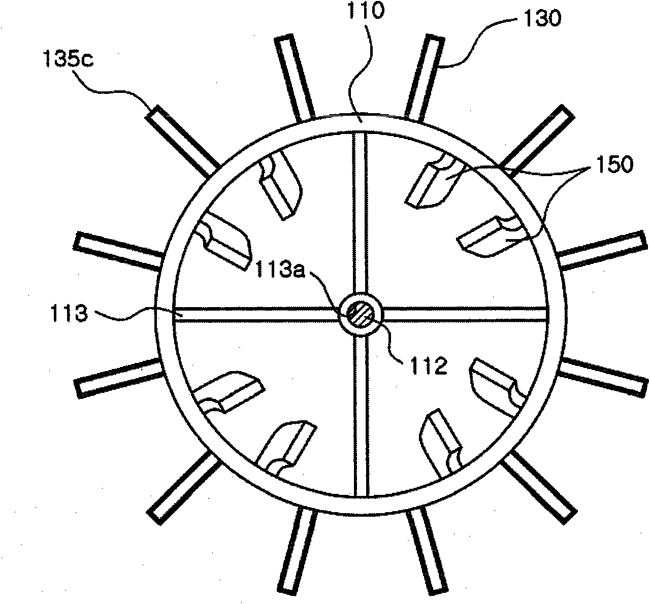
[0041] figure 1 is a configuration diagram showing a local exhaust system capable of controlling turbulence according to a first exemplary embodiment of the present invention, and FIG. 2( a ) is along figure 1 The front view taken in the direction of the arrow A in Fig. 2(b) is along the figure 1 Front view taken in the direction of arrow B in, image 3 is an exploded perspective view showing a local exhaust system capable of controlling turbulence according to a first exemplary embodiment of the present invention.

[0042] like Figures 1 to 3 As shown in , the local exhaust system 100 according to the first exemplary embodiment of the present invention includes an exhaust pipe 101 , a motor 109 , a rotor structure 110 and turbulence-generating outer blades 130 .

[0043] The exhaust pipe 101 may b...


PUM


Abstract

Provided is a local exhaust apparatus. The local exhaust apparatus comprises: a motor member which is installed in an exhaust pipe for guiding and discharging air sucked through an intake port and generates torque when powered, a rotary structure which is located on the leading end of the intake port to rotate with the center of the exhaust pipe as a rotation center and connects to the drive shaft of the motor member, and exterior blades for swirling which are assembled by the medium of an angle adjusting member provided on the exterior of the rotary structure so that the angle of the air intake direction through the intake port can be adjusted and create swirls when rotated. The present invention enables the user to simply regulate the installation angle of the exterior blades generating swirls in order to control the intake area properly according to the intake range of a place to emit exhaust and enables simultaneous generation of swirls and intake-exhaust force using a single drive source.

Description

technical field [0001] The present invention relates to a local exhaust system, and more particularly, to a local exhaust system in which turbulent flow can be controlled simply by adjusting the angle of the turbulence-generating vanes so that the intensity and extent of the turbulent flow can be adjusted according to the pollution source Certain conditions are appropriately changed while the turbulence generating vane and the intake-exhaust vane are driven and rotated by one drive source. Background technique [0002] Generally, a local exhaust system is a set of equipment installed in factories, restaurants, etc. where pollutants are often generated. The local exhaust system is used to provide intake-exhaust force to the inlet as one end of the exhaust pipe, thereby exhausting polluted air from the room to the outside. [0003] Local exhaust systems can be effectively used in situations where: where the local pollution source is located in the bottom area away from the ai...

Claims


Application Information

Patent Timeline
Patent Type & Authority Applications(China)
IPC IPC(8): F24F13/08F24F13/06
CPCF24F13/06F24F2013/1433F24C15/20F24F13/08
Inventor 卢灿荣金学承赵兴元尹泳铁李张烈
Owner GTEC
Why Eureka
Try Eureka