Vacuum valve

A vacuum valve and valve core technology, which is applied to lift valves, valve details, safety valves, etc., can solve the problems of changing the bending amount of the annular sealing member 122 and restricting the position movement.

Active Publication Date: 2012-05-02
CKD
View PDF4 Cites 0 Cited by
  • Summary
  • Abstract
  • Description
  • Claims
  • Application Information

AI Technical Summary

Problems solved by technology

The second piston 115 can rise to abut against the lower end of the adjustment handle 119, and the positional movement is restricted
[0020] In addition, the annular sealing member 122 deteriorates after being repeatedly used, and the bending amount of the annular sealing member 122 changes when the valve is closed.

Method used


Image

  • Vacuum valve
  • Vacuum valve
  • Vacuum valve

Examples


Embodiment Construction

[0063] Hereinafter, one embodiment of the vacuum valve according to the present invention will be described with reference to the drawings.

[0064]

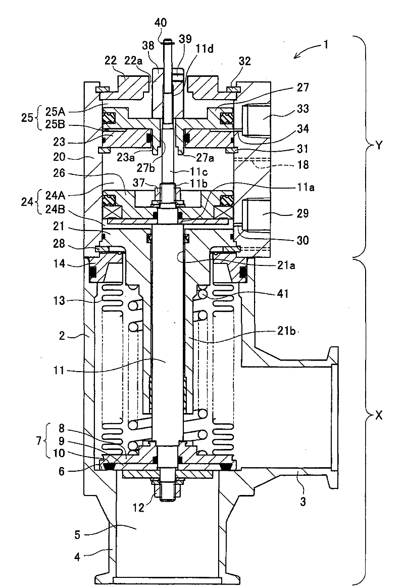
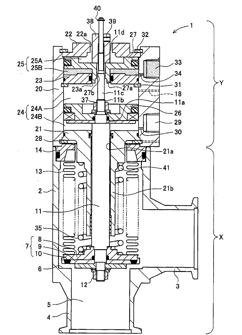
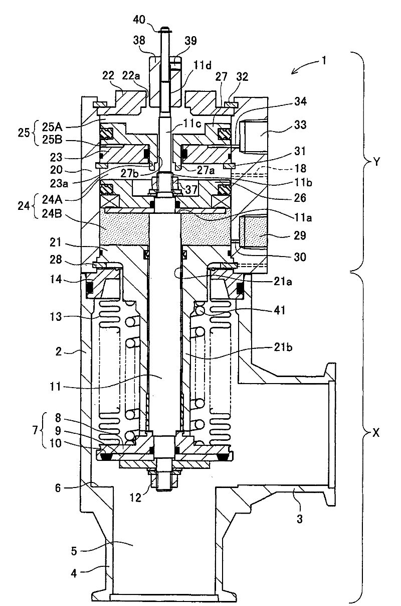
[0065] Figure 1 to Figure 3 It is a sectional view showing an embodiment of the vacuum valve 1, figure 1 is a diagram showing the closed valve state, figure 2 is a graph representing a slow exhaust state, and image 3 is a diagram showing a rapid exhaust state. for Figure 1 to Figure 3 In all cases, the stroke adjustment member 38 is arranged at the lowest position. and, Figure 4 for figure 1 The top view of the vacuum valve 1 shown.

[0066] Figure 1 to Figure 4 The shown vacuum valve 1 is disposed between a chamber of a semiconductor manufacturing apparatus and a vacuum pump, as in the prior art.

[0067] Such as Figure 1 to Figure 3 As shown, the vacuum valve 1 is composed of a lower valve part X and an upper driving part Y. The vacuum valve 1 changes the stroke of the spool 7 by moving the first piston 2...


PUM


Abstract

The invention provides a vacuum valve that can simply and correctly adjust origin position of a stroke adjustment element even through the product is assembled. The vacuum valve (1) drives a first piston (26) and a second piston (27) to move independently to change stroke of a spool valve (7) to control flow in stage. The vacuum valve (1) screws the stroke adjustment element (38) to an adjustmentnut portion (11d) till the stroke adjustment element contacts the second piston (27) in a state that the second piston (27) bears against an upper cover (22). The stroke adjustment element (38) is fixed by a fix bolt (39) to adjust origin position of the stroke adjustment element.

Description

technical field [0001] The present invention relates to a vacuum valve capable of controlling the exhaust flow rate in stages, for example, when performing vacuum exhaust in a vacuum chamber of a semiconductor manufacturing apparatus. Background technique [0002] In semiconductor manufacturing equipment, when the vacuum exhaust in the vacuum chamber is carried out, because the gas in the vacuum chamber is quickly exhausted, a large amount of gas flows in a short period of time, resulting in particles (dust) attached to the inner wall of the vacuum chamber and the flow path. ) is rolled up. In addition, if the exhaust flow rate is reduced too much, the exhaust time will become longer, which will have a bad influence on the production tact. Therefore, for example, Patent Document 1 proposes a vacuum valve that prevents entrainment of particles by switching the exhaust flow rate from a small flow rate to a large flow rate. [0003] Figure 7 to Figure 9 It is a sectional vie...

Claims


Application Information

Patent Timeline
Patent Type & Authority Patents(China)
IPC IPC(8): F16K1/02F16K1/52F16K17/36F16K31/00
CPCF16K51/02H01L21/67017
Inventor 内藤正博伊藤慎市川雅规小洞匡博
Owner CKD
Why Eureka
Try Eureka