
Drive control circuit and electronic equipment

A driving control circuit and brightness control technology, applied in the field of electronics, can solve the problems of low luminous efficiency, large OLED driving current, short service life, etc.

Active Publication Date: 2011-02-09
HISENSE VISUAL TECH CO LTD
View PDF3 Cites 9 Cited by
  • Summary
  • Abstract
  • Description
  • Claims
  • Application Information

AI Technical Summary

Problems solved by technology

[0010] Embodiments of the present invention provide a drive control circuit on the one hand, and provide an electronic device equipped with the drive control circuit on the other hand, which solves the problem that the existing passive drive control circuit causes the OLED to continuously flicker at high frequency. Technical problems of low luminous efficiency, large driving current required by OLED and short service life

Method used


Image

  • Drive control circuit and electronic equipment
  • Drive control circuit and electronic equipment
  • Drive control circuit and electronic equipment

Examples


Embodiment Construction

[0060] The technical solutions in the embodiments of the present invention will be clearly and completely described below with reference to the accompanying drawings in the embodiments of the present invention. Obviously, the described embodiments are only a part of the embodiments of the present invention, but not all of the embodiments. Based on the embodiments of the present invention, all other embodiments obtained by persons of ordinary skill in the art without creative efforts shall fall within the protection scope of the present invention.

[0061] Embodiments of the present invention provide a driving control circuit that can make the OLED light up for a long time, has high luminous efficiency, small driving current required by the OLED, and has a long service life, and an electronic device provided with the driving control circuit.

[0062] like figure 2 As shown, the driving control circuit provided by the embodiment of the present invention includes a decoding modu...


PUM


Abstract

The invention provides a drive control circuit and electronic equipment, relating to the technical field of electronics. The invention solves the following technical problems: OLED in the prior art has to flicker continuously under high frequency, has low light-emitting efficiency, needs higher drive current and has short service life. The drive control circuit comprises a decoding module, a data processing module and a drive module, wherein the data processing module is used for processing the RGB signal and the control signal into the row gate voltage signal in the digital signal format, the line gate voltage signal in the digital signal format and the brightness control signal in the analog signal format and for inputting the row gate voltage signal, the line gate voltage signal and the brightness control signal into the drive module according to certain time sequence; and the drive module is used for gating the scanning lines and the data lines of an AM-OLED display screen and controlling the brightness of OLED in the pixel of the AM-OLED display screen via the brightness control signal. The electronic equipment comprises the drive control circuit. The invention is applied to the OLED display screen.

Description

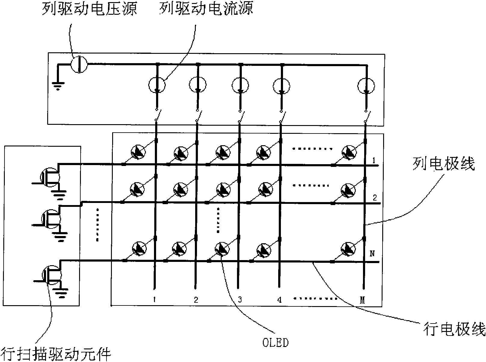
technical field [0001] The invention relates to the field of electronic technology, in particular to a drive control circuit and electronic equipment provided with the drive control circuit. Background technique [0002] Along with the rapid development of electronic technology, TV sets have become one of the most common household appliances in people's daily life. [0003] like figure 1 As shown, the existing TV includes a display screen and a passive (Passive-Matrix) drive control circuit. The display screen is a matrix composed of a single OLED (Organic Light-Emitting Diode, Organic Light-Emitting Diode), three OLEDs that emit red light, green light, and blue light respectively form an RGB pixel. The anode of each OLED is connected in parallel with the anodes of other OLEDs in the same column, and the cathode is connected in parallel with the cathodes of other OLEDs in the same row. [0004] When a low level is applied to the row where an OLED is located and a high leve...

Claims


Application Information

Patent Timeline
IPC IPC(8): H04N5/64G09G3/32G09G3/3233
Inventor 宋林张钰枫郭好磊
Owner HISENSE VISUAL TECH CO LTD
Learn More