Intraoral LED illumination device with biteblock

A technology of oral lighting and LED light source, applied in the fields of oral mirror, application, medical science, etc., to prevent secondary infection and ensure the doctor's sight.

Inactive Publication Date: 2011-02-09
DENTOZONE
View PDF7 Cites 3 Cited by
  • Summary
  • Abstract
  • Description
  • Claims
  • Application Information

AI Technical Summary

Problems solved by technology

[0021] When the battery of the above-mentioned lighting equipment and surgical lighting equipment runs out early when the doctor is treating the patient, it is necessary to take out the above-mentioned lighting equipment and surgical lighting equipment from the inside of the oral cavity to replace or charge the battery, which causes great inconvenience

Method used


Image

  • Intraoral LED illumination device with biteblock
  • Intraoral LED illumination device with biteblock
  • Intraoral LED illumination device with biteblock

Examples


Embodiment Construction

[0050] The terminology in the present invention should choose the general term widely used now as much as possible, and there are also terms arbitrarily selected by the applicant under certain circumstances. its semantics and grasp its meaning.

[0051] The technical constitution of the present invention will be described in detail below with reference to the accompanying drawings.

[0052] However, the implementation of the present invention is not limited to the description here, and can also be embodied in other forms, and the same number appearing in the entire description corresponds to the same constituent element.

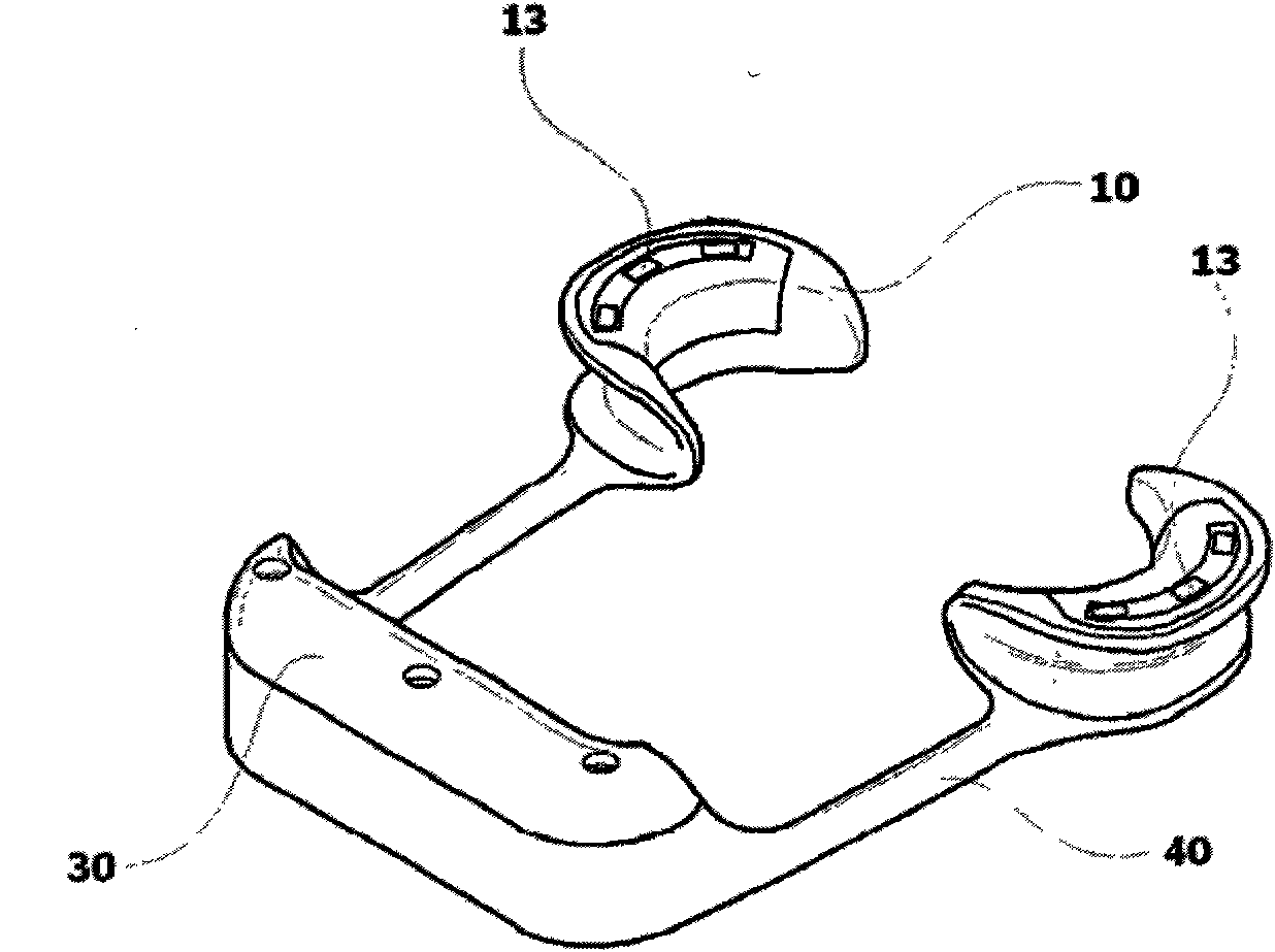
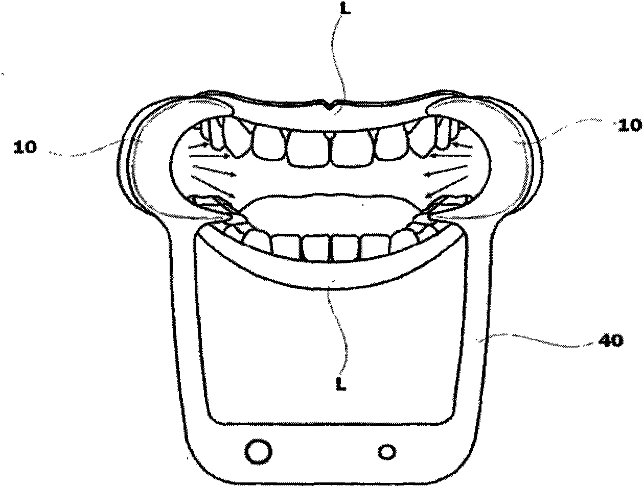
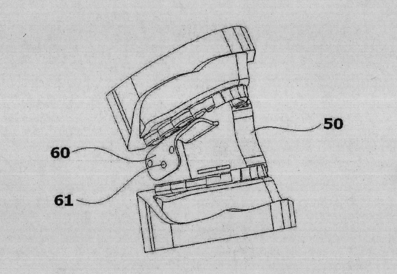
[0053] Figure 5 is a schematic diagram of an LED oral lighting device in an embodiment of the present invention, Figure 6 It is an exploded schematic view of the frame and tooth pad of the LED oral lighting device in an embodiment of the present invention, Figure 7 It is a schematic diagram of the use state of the LED oral cavity lighting device in an ...


PUM


Abstract

The invention discloses an intraoral LED illumination device with a biteblock, which comprises a U-shaped bending frame and a biteblock connected with one end of the frame, wherein, an LED light source and a light source switch of controlling the switching on-off of the light source are fixed on one end of the frame.

Description

technical field [0001] The invention belongs to the field of oral lighting equipment, and in particular relates to a battery for power supply and a tooth pad for improving the opening of the oral cavity by utilizing the LED oral lighting equipment. Background technique [0002] Generally speaking, in order to perform dental treatment in dentistry, the patient is first let the patient lie on the special dental treatment chair, and the patient's oral cavity is illuminated by the lighting device on the special dental treatment chair to ensure the doctor's sight. [0003] The doctor uses the above-mentioned lighting device to illuminate the affected part of the patient's oral cavity, and uses scrubbers, high-speed handpieces, scrapers, low-speed handpieces, etc. to perform diagnosis and treatment. [0004] On the other hand, the characteristic of dental diagnosis and treatment is that the patient's tooth affected area is very small and there are many nerves around it, which requ...

Claims


Application Information

Patent Timeline
Patent Type & Authority Applications(China)
IPC IPC(8): A61B1/24
CPCA61B1/00034A61B1/07A61B1/0684A61B1/24A61B1/0669
Inventor 具滋亨
Owner DENTOZONE
Why Eureka
Try Eureka