
Turbidity measuring device and a method for determing a concentration of a turbidity-causing material

A measurement device, turbidity technology, applied in the direction of measurement device, scattering characteristic measurement, suspension and porous material analysis, etc., can solve the problems of weak FAL signal, difficult to accurately determine the concentration of turbidity substances, etc.

Active Publication Date: 2011-02-02
ENDRESS HAUSER CONDUCTA GESELLSCHAFT FUER MESS UND REGELTECHNIK MBH CO KG
View PDF5 Cites 6 Cited by
  • Summary
  • Abstract
  • Description
  • Claims
  • Application Information

AI Technical Summary

Problems solved by technology

In the case of low concentrations, below a single measuring channel S ij , but the FAL signal is weaker, which makes it difficult to accurately determine the concentration of the turbidity-causing species because (as given by Equation 5) for low concentrations, the variable FAL(T) converges towards a constant C such that The correlation to the concentration T of the turbidity-causing substance is practically no longer given

Method used


Image

  • Turbidity measuring device and a method for determing a concentration of a turbidity-causing material
  • Turbidity measuring device and a method for determing a concentration of a turbidity-causing material
  • Turbidity measuring device and a method for determing a concentration of a turbidity-causing material

Examples


Embodiment Construction

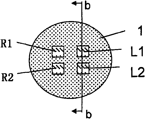
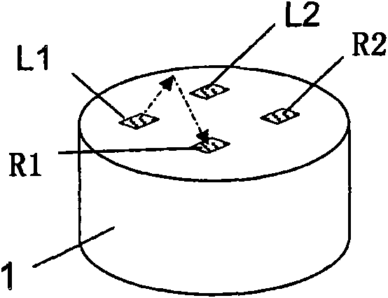
[0044] Figure 1a The probe of the turbidity measuring device shown consists of a substantially cylindrical metal housing made of stainless steel, at the ends of which are provided four windows (the corners of which define a rectangle), which direct the first light source L 1 and the second light source L 2 , the first receiver R 1 and the second receiver R 2 Sealed away from the environment surrounding the probe; wherein the first light source L 1 and the second light source L 2 Radiant energy enters and exits through the window.

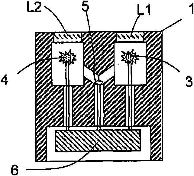
[0045] Such as Figure 1b As shown, the light source L 1 and L 2 It includes a first flashlight 3 and a second flashlight 4, wherein monitoring diodes 5 are arranged between the flashlights, and the distribution records the light intensity of the first flashlight and the second flashlight.

[0046] The first flashlight 3, the second flashlight 4 and the monitoring diode 5 and the first receiver R 1 and the second receiver R 2 Each photodi...


PUM


Abstract

The invention discloses a turbidity measuring device and a method for determing a concentration of a turbidity-causing material. The turbidity measuring device includes first and second light sources L1, L2; and first and second receivers R1, R2. The direct measuring paths extend from light sources Li, through a measured medium, to receivers Ri, and indirect measuring paths extend from light sources Li, through the measured medium, to second receivers Rj; wherein i is not equal to j; wherein turbidity can be ascertained as a function of a quotient A / B by means of an evaluating circuit; wherein A and B are functions at least of signals registered via the direct or indirect measuring paths; wherein at least a first monitor signal, which depends on the first light source, enters into one of the two terms A or B; wherein the light reaches the monitor from the first light source without interaction with the measured medium; and wherein the monitor signal is added to at least one of the signals registered via the measuring paths and entering into the term A or B.

Description

technical field [0001] The invention relates to a turbidity measuring device and a method for determining the concentration of a substance causing turbidity in a medium, in particular to a turbidity measuring device based on the principle of four-beam alternating light and the method using the principle of four-beam alternating light Methods. Background technique [0002] The turbidity measuring device according to the four-beam alternating light principle comprises at least two light sources and at least two receivers, wherein four measurement paths are defined between the two measurement sources and the two receivers, through which , the light emitted by the light source reaches the receiver; where in at least two measurement paths the light reaches the receiver by scattering. Generally, after interacting with the measurement medium, the received light source L i Receiver R of emitted light j signal S ij (T) is given by Equation 1. [0003] S ...

Claims


Application Information

Patent Timeline
Patent Type & Authority Applications(China)
IPC IPC(8): G01N15/06G01N21/00
CPCG01N2201/0662G01N15/06G01N21/274G01N2201/061G01N21/53G01N2015/0693G01N15/075
Inventor 鲁迪格尔·弗兰克安德烈亚斯·米勒
Owner ENDRESS HAUSER CONDUCTA GESELLSCHAFT FUER MESS UND REGELTECHNIK MBH CO KG
Learn More