
Annular air duct end sealing transition region liquid prevention and wave suppression device

A technology of end sealing and annular air duct, which is applied in the field of annular coolers, and can solve problems such as sticking ash and agglomeration of the grate plate of the trolley, resetting, and affecting the cooling of the grate plate ventilation material, etc.

Active Publication Date: 2011-02-02
ZHONGYE-CHANGTIAN INT ENG CO LTD
View PDF5 Cites 0 Cited by
  • Summary
  • Abstract
  • Description
  • Claims
  • Application Information

AI Technical Summary

Problems solved by technology

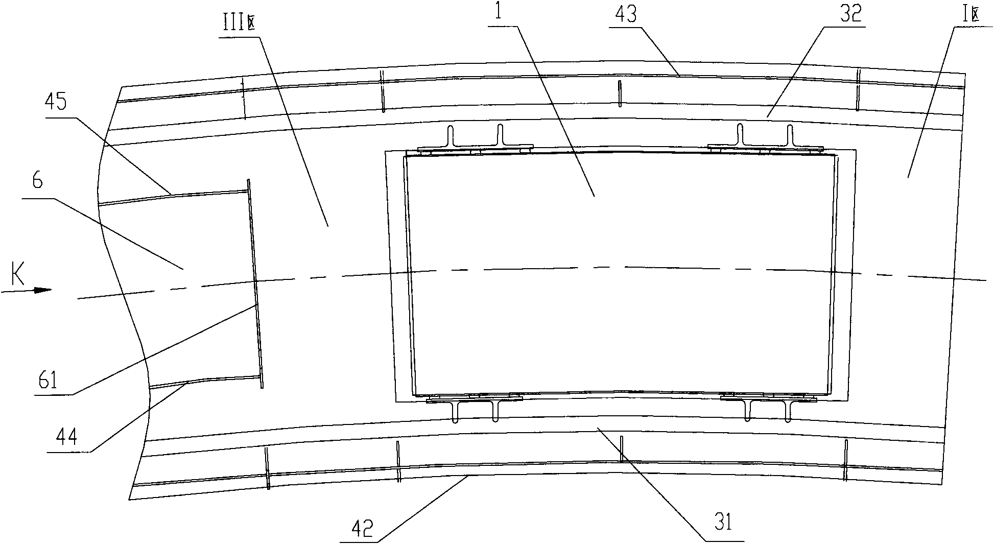
[0008] The door-shaped sealing device 3 of the annular air duct moves with the trolley. When the air outlet on the door-shaped sealing device cover plate 33 passes through the end seal transition zone III, the liquid in the annular liquid tank 4 will flow with the wind. Entering the trolley, the liquid entering the trolley will cause the grate plate of the trolley to stick to ash and agglomerate, which will affect the ventilation of the grate plate and the cooling of the material.

Method used


Image

  • Annular air duct end sealing transition region liquid prevention and wave suppression device
  • Annular air duct end sealing transition region liquid prevention and wave suppression device
  • Annular air duct end sealing transition region liquid prevention and wave suppression device

Examples


Embodiment Construction

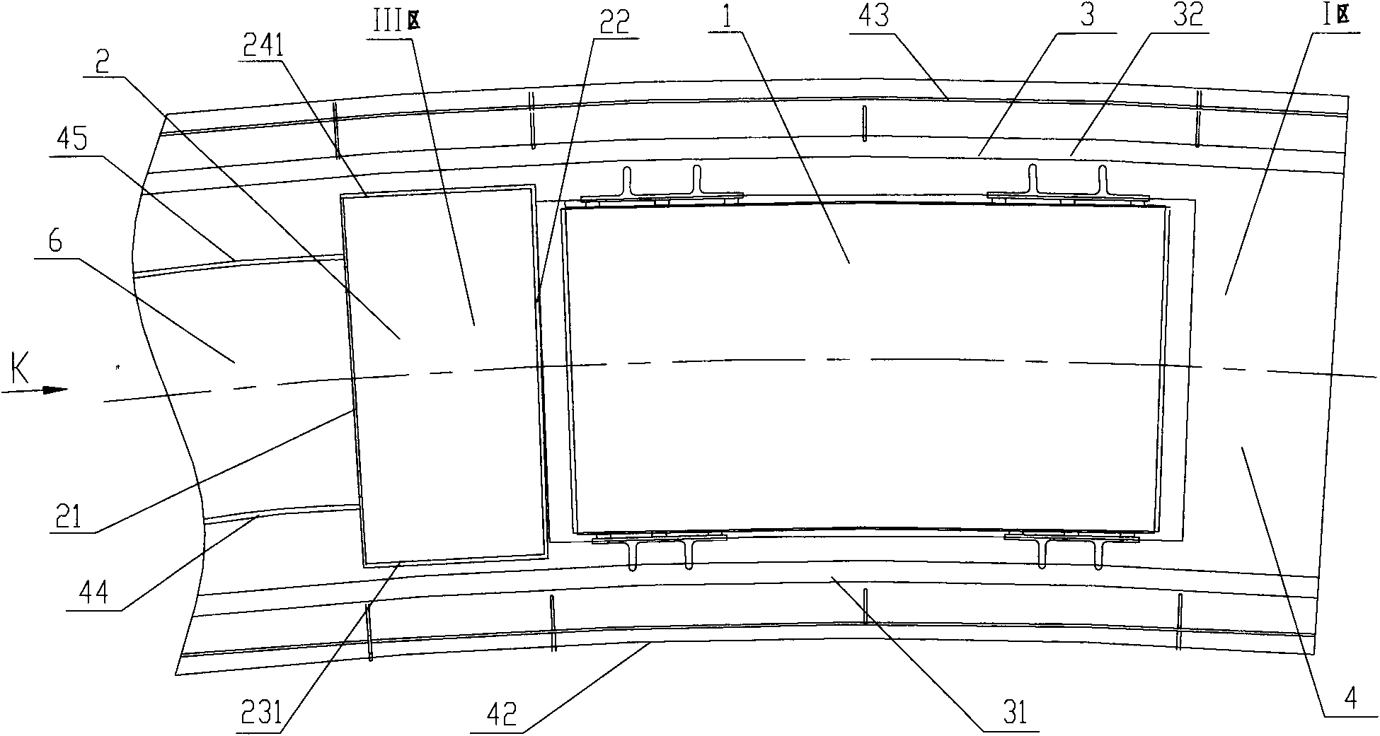
[0031] The object of the present invention is to provide a liquid-proof and wave-suppressing device for the sealing transition area at the end of the annular air duct, which is used to prevent the liquid from entering the trolley in the sealing transition area at the end of the annular air duct with the wind.

[0032] In order to make the above-mentioned purposes, features and advantages of the present invention more obvious and easy to understand, the liquid-proof and wave-suppressing device for the sealing transition zone at the end of the annular air duct of the present invention will be further described in detail below in conjunction with the accompanying drawings and specific embodiments.

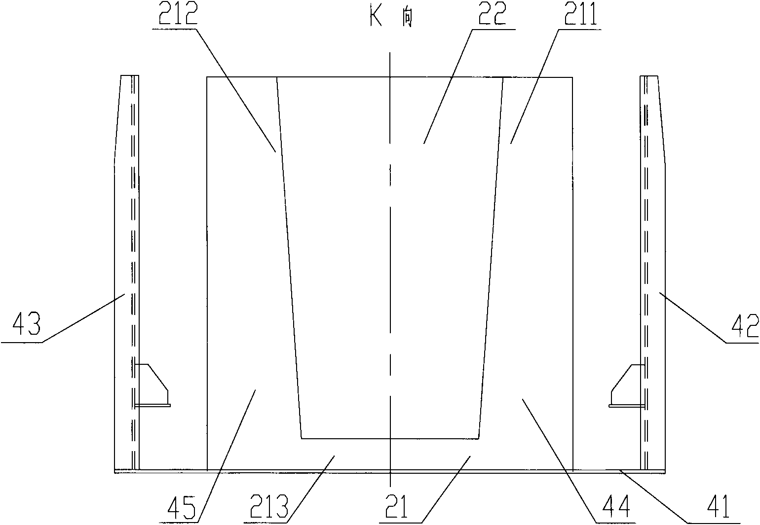
[0033] see figure 2 , image 3 , figure 2 It is a top view of the liquid-proof and wave-suppressing device in the sealing transition zone at the end of the annular air duct according to the embodiment of the present invention; image 3 yes figure 2 The view from direction K is s...


PUM


Abstract

The invention discloses an annular air duct end sealing transition region liquid prevention and wave suppression device. The device comprises a liquid prevention and wave suppression device end plate and a connecting plate which are fixedly arranged on a liquid groove bottom plate, wherein the liquid prevention and wave suppression device end plate is a blind plate which is arranged close to an annular air duct end sealing device in the radial direction; the connecting plate is arranged to be a U-shaped structure along the radial direction; the liquid prevention and wave suppression device end plate and the connecting plate have the same height as an inner annular plate of an annular liquid groove air duct; an inner annular plate and an outer annular plate of the liquid prevention and wave suppression device are arranged at the bottom of the annular liquid groove between the liquid prevention and wave suppression device end plate and the connecting plate; the inner annular plate and the outer annular plate of the liquid prevention and wave suppression device have the same height as the liquid prevention and wave suppression device end plate; the radial width of the connecting plate is greater than the distance between the inner annular plate and the outer annular plate of the annular liquid groove air duct and is a preset distance away from the inner annular plate and the outer annular plate of a door-shaped air duct; and when the door-shaped sealing device moves, the inner annular plate and the outer annular plate of the liquid prevention and wave suppression device move relative to the inner annular plate and the outer annular plate of the door-shaped air duct. The invention provides the annular air duct end sealing transition region liquid prevention and wave suppression device which prevents the liquid at the annular air duct end sealing transition region from entering a trolley.

Description

technical field [0001] The invention relates to the field of annular coolers, in particular to a liquid-proof and wave-suppressing device for the sealing transition area at the end of an annular air duct. Background technique [0002] The dynamic sealing of the annular air duct of the annular cooler is realized by the liquid sealing method of the annular air duct. Specifically, the dynamic sealing of the annular air duct is realized by the fixedly installed annular liquid tank and the door-type sealing device matched with the annular liquid tank. A plurality of through holes are opened at the bottom of the annular liquid tank in the cooling zone to facilitate the passage of cooling air. The radial section of the door-shaped sealing device is door-shaped, and the cover plate of the door-shaped sealing device is provided with an air outlet connected to the air inlet pipe of the trolley. The door-shaped air channel inner ring plate and the door-shaped air channel outer ring pl...

Claims


Application Information

Patent Timeline
IPC IPC(8): F27D15/02
Inventor 高德亮戴传德
Owner ZHONGYE-CHANGTIAN INT ENG CO LTD
Learn More