Three-directional composite self-lubricating sliding bearing for main shaft of wind turbine set
A technology for wind turbines and sliding bearings, applied in sliding contact bearings, shafts and bearings, bearing components, etc., can solve the problems of increased frictional resistance, low bearing reliability, fatigue crushing and crushing, etc., and achieves extended service life and simple structure. The effect of compactness and improved stress state
- Summary
- Abstract
- Description
- Claims
- Application Information
AI Technical Summary
Problems solved by technology
Method used
Image
Examples
Embodiment 1
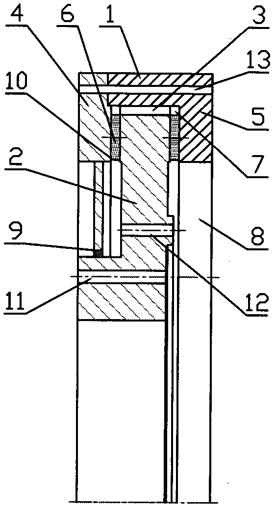
[0022] Such as figure 1 Shown: Same as the prior art, there is an outer ring 1 of a fixed part and an inner ring 2 of a rotating part, and there are a plurality of radial tiles 3 evenly distributed on the circumference between the outer ring 1 and the inner ring 2, and the radial tiles 3 are fixed On the inner surface of the outer ring 1, the inner ring 2 is provided with a connection hole 11 connected to the hub and a connection hole 12 connected to the gearbox in the wind turbine. The difference from the prior art is that the outer ring 1 is axially The left side is connected with the inward left thrust ring 4, and the inward right thrust ring 5 is connected with the axial right side of the outer ring 1. The right thrust ring 5 can be integrated with the outer ring 1, and the left thrust ring 4. The outer circumference can be connected with the outer ring 1 through bolt holes 13, etc., and seals or sealants are arranged at the joint. The inner hole of the left thrust ring 4 ...
Embodiment 2
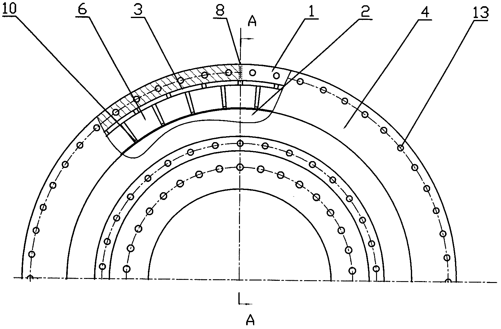
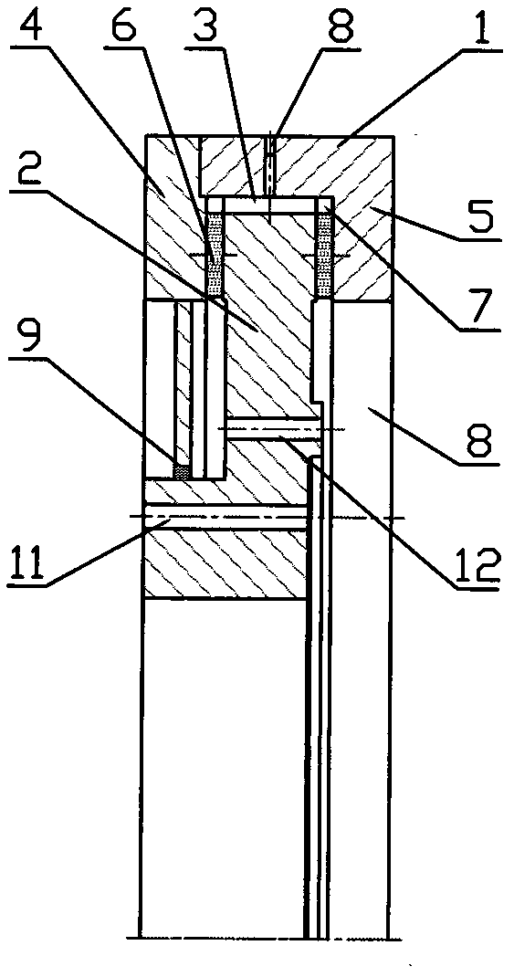
[0025] Such as figure 2 , image 3 As shown, in order to further improve the lubricating effect, on the basis of Embodiment 1, an oil injection hole 8 can be added in the radial direction of the outer ring 1 . During work, the lubricating oil can enter the three pairs of friction pairs through the radial oil hole of the outer ring 1 and the inner hole of the right thrust ring 5 to lubricate.
Embodiment 3
[0027] Such as Figure 4 , Figure 5 Shown: Same as the prior art, there is an outer ring 1 of a fixed part and an inner ring 2 of a rotating part, and there are a plurality of radial tiles 3 evenly distributed on the circumference between the outer ring 1 and the inner ring 2, and the radial tiles 3 can be It is fixed on the inner surface of the outer ring 1, and can also be fixed on the outer surface of the inner ring 2. The inner ring 2 is provided with a connecting hole 11 connected with the hub. The difference from the prior art is that the axis of the outer ring 1 is left There is an inward left thrust ring 4 on the side, and an inward right thrust ring 5 is connected to the axial right side of the outer ring 1. The right thrust ring 5 can be integrated with the outer ring 1, and the left thrust ring 4 The outer circumference can be connected with the outer ring 1 through bolt holes 13, etc., and seals or sealants are arranged at the joints. The inner holes of the left ...
PUM
 Abstract
Description
Claims
Application Information
 - R&D
- Intellectual Property
- Life Sciences
- Materials
- Tech Scout
- Unparalleled Data Quality
- Higher Quality Content
- 60% Fewer Hallucinations
Browse by: Latest US Patents, China's latest patents, Technical Efficacy Thesaurus, Application Domain, Technology Topic, Popular Technical Reports.
© 2025 PatSnap. All rights reserved.Legal|Privacy policy|Modern Slavery Act Transparency Statement|Sitemap|About US| Contact US: help@patsnap.com


