
Control device of a transversing gear

A technology of traversing device and control device, applied in the directions of transportation and packaging, textile and papermaking, thin material processing, etc., can solve the problems of non-elimination, offset, and package non-uniformity.

Active Publication Date: 2011-02-02
TMT MACHINERY INC
View PDF6 Cites 4 Cited by
  • Summary
  • Abstract
  • Description
  • Claims
  • Application Information

AI Technical Summary

Problems solved by technology

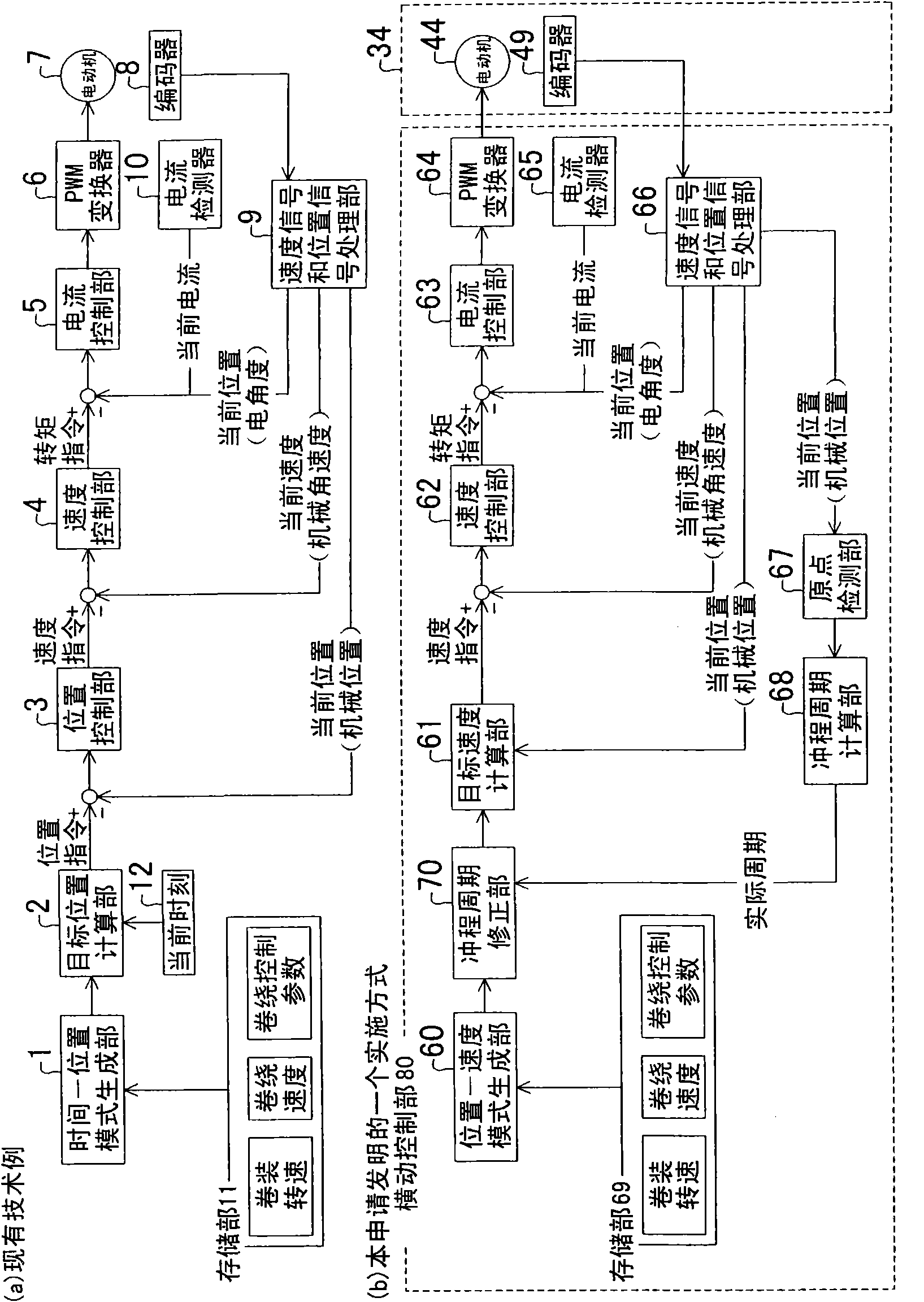
[0006] However, since the above-mentioned B control device gives priority to the current position of the yarn carrier over the running speed of the yarn carrier, in order to make the current position of the yarn carrier consistent with the desired one, the running speed of the yarn carrier fluctuates up and down, which causes production problems. The non-uniformity of the package density in the axial direction
More specifically, in the case of using the above-mentioned B control device, if the fluctuation of the running speed of the yarn carrier occurs irregularly and randomly to a certain extent, the unevenness of the density of the package in the axial direction may almost cancel out.
However, in fact, from the fact that the inventors of the present application have experimentally implemented the above-mentioned B control device, it has been confirmed that the fluctuation of the running speed of the yarn carrier always occurs in the same way, and it has not been eliminated so far. The regularity

Method used


Image

  • Control device of a transversing gear
  • Control device of a transversing gear
  • Control device of a transversing gear

Examples


Embodiment Construction

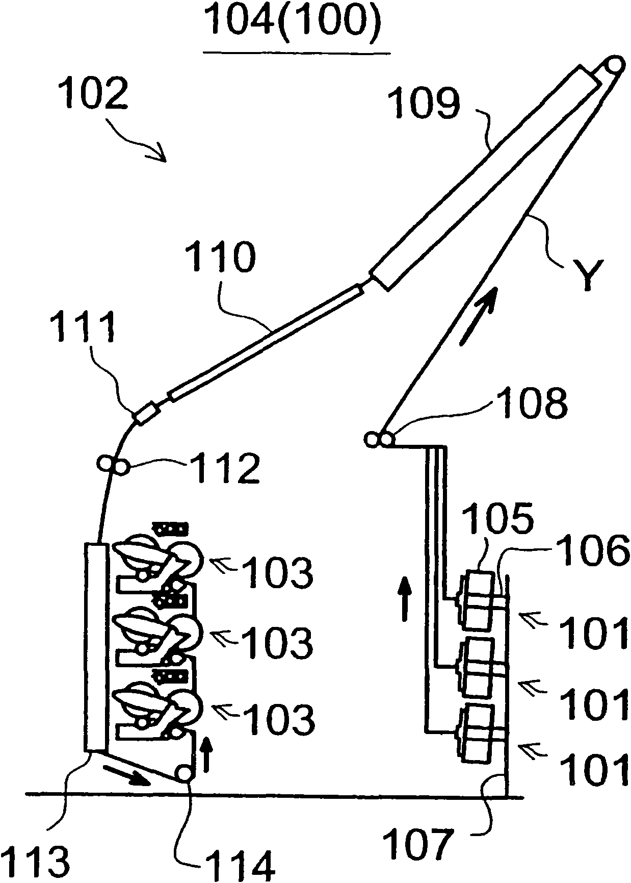
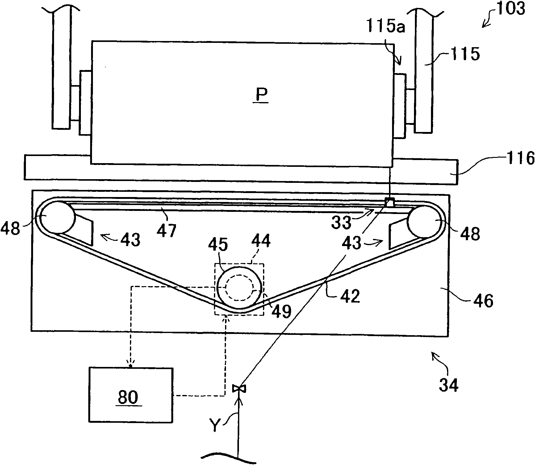
[0018] Below as an example based on Figure 1~3 An embodiment in which the traversing device according to the invention of the present application is used in a winding section of a draw false twisting machine will be described.

[0019] like figure 2 As shown, the drawing false twisting processing machine 100 is constituted by a plurality of processing units 104 (also referred to as "spindles"). The processing section 102 for stretching and false twisting processing and the winding section 103 for winding the processed yarn Y to form a package are constituted. The above-mentioned processing unit 104 is along with figure 2 The vertical direction of the drawings is arranged side by side. However, in order to save space, the yarn supplying unit 101 and the winding unit 103 are arranged so that 2 to 4 spindles are stacked up and down.

[0020] The yarn supplying unit 101 is provided with a bobbin 106 holding the yarn supplying package 105 , and each bobbin 106 is attached to...


PUM


Abstract

The invention relates to a control device of a transversing gear capable of eliminating the axial nonuniformity of the package density. A transversing control part (80) of the transversing gear (34) comprises a position-speed mode generation part (60) for supplying the relation between the position of a yarn guide (33) and the walking speed of the yarn guide (33) at the position, namely position-speed mode; an object speed calculation part (61) for calculating the object walking speed of the yarn guide (33) based on the position-speed mode supplied by the position-speed mode generation part (60) and the current position of the yarn guide (33) detected by a coder (49); and a drive control unit for controlling the action of a drive unit of the yarn guide based on the walking speed calculated by the object speed calculation part (61).

Description

technical field [0001] The invention relates to a control device for a traversing device for traversing a yarn. Background technique [0002] As such a technique, Patent Document 1 discloses a method capable of controlling an accurate position of a yarn guide of a traverse device. Specifically, the current position of the yarn guide is monitored and compared with a predetermined target position, and the running speed of the yarn guide is adjusted to eliminate the deviation. Please refer to Claim 1, Claim 2, paragraph numbers 0005, 0009 and 0011 of Patent Document 1 if necessary. [0003] [Patent Document 1] Japanese Patent No. 4155705 [0004] The control block diagram of the control device (hereinafter referred to as B control device) of the traverse device disclosed in the above document 1 is as follows: figure 1 (a) You reproduced it like that, please refer to it. [0005] like figure 1 As shown in (a), the B control device is mainly composed of a time-position patte...

Claims


Application Information

Patent Timeline
IPC IPC(8): D01H7/04D01H13/04B65H54/36
CPCB65H54/2818B65H54/2887B65H2701/31B65H54/2827B65H54/2821
Inventor 长谷川正胜播户志郎
Owner TMT MACHINERY INC
Learn More