
Minicar impact-proof beam energy absorption box capable of controlling impact energy absorption and residual deformation

A technology for residual deformation and small cars, which is applied to vehicle components, bumpers, and substructures, etc. It can solve the problems of reduced energy absorption, difficulty in controlling the deformation process of the structure of the energy-absorbing box and energy absorption, and difficulty in achieving balance. The effect of improving safety performance

Active Publication Date: 2011-02-02
LINGYUN INDAL CORP
View PDF6 Cites 18 Cited by
  • Summary
  • Abstract
  • Description
  • Claims
  • Application Information

AI Technical Summary

Problems solved by technology

Most of the existing energy-absorbing boxes have guide ribs with irregular structures on the box body. It is difficult to control the deformation process and energy absorption of the structure of the energy-absorbing box when such guide ribs collide. Usually, when the energy is absorbed for a long time, the The amount of crushing is very large, and when reducing the amount of guiding ribs to reduce the amount of crushing, the energy absorption is reduced, and it is difficult to achieve a balance

Method used


Image

  • Minicar impact-proof beam energy absorption box capable of controlling impact energy absorption and residual deformation
  • Minicar impact-proof beam energy absorption box capable of controlling impact energy absorption and residual deformation
  • Minicar impact-proof beam energy absorption box capable of controlling impact energy absorption and residual deformation

Examples


Embodiment Construction

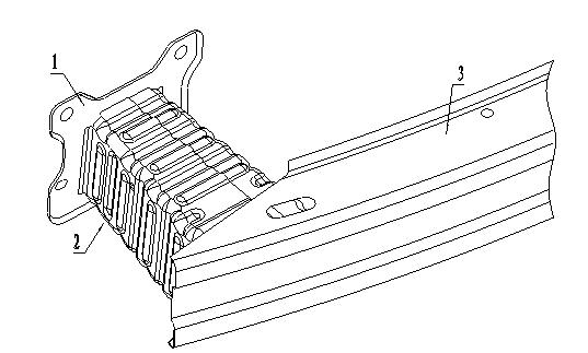
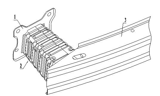
[0013] see figure 1 , the present invention comprises beam 3 and energy-absorbing box 2, and energy-absorbing box 2 is similar to bucket shape, and it is symmetrically installed on beam two ends, and its large port is welded with beam, and small port is welded with mounting plate 1.

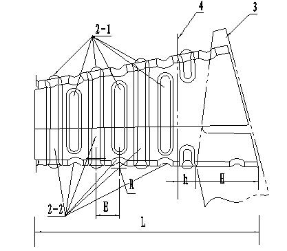
[0014] see figure 1 , figure 2 , the technical gist of the present invention is to improve the guide ribs on the energy-absorbing box, the energy-absorbing box 2 is provided with regularly distributed convex and concave guide ribs, and the regularly distributed convex and concave guide ribs are set as follows: Convex guide ribs 2-1 and concave guide ribs 2-2 are arranged alternately on each side wall of the energy-absorbing box, wherein the positions of the concave and convex guide ribs on the opposite side walls of the energy-absorbing box correspond; two adjacent energy-absorbing boxes The positions of the concave guide ribs on the side wall correspond to the positions of the convex guide ri...


PUM

PropertyMeasurementUnit
Arc radius raaaaaaaaaa

Abstract

The invention relates to a minicar impact-proof beam energy absorption box capable of controlling impact energy absorption and residual deformation, which is used for solving the problem of the energy absorption of a front impact-proof beam and comprises a transverse beam and energy absorption boxes symmetrically arranged on both sides of the transverse beam, wherein the improved energy absorption boxes are provided with bulged and concave guide tendons regularly distributed; the bulged guide tendons and the concave guide tendons are alternately arranged on the side walls of the energy absorption boxes; the positions of the bulged and the concave guide tendons on the two relative side walls of the energy absorption boxes are corresponding; and the positions of the bulged and the concave guide tendons on the two adjacent side walls of the energy absorption boxes are corresponding. The invention has the advantages that the guide tendons regularly distributed are successively squashed and absorb energy when the front impact-proof beam of an automobile is impacted through the optimization design of the guide tendons arranged on the energy absorption boxes, and the front impact-proof beam presents an S-shaped squashing type when deforming; the energy absorption can be satisfied, and the height of the energy absorption boxes after deforming can be effectively overlaid and supported at the same time; the residual deformation of the energy absorption boxes after squashing can be guaranteed; and the deformation mode of the energy absorption box basically coincide to the expected design through CAE analysis and test confirmation.

Description

technical field [0001] The invention relates to a vehicle device, in particular to a front anti-collision beam energy-absorbing box structure suitable for various small cars and capable of effectively controlling energy absorption and residual deformation, and belongs to the technical field of automobiles. Background technique [0002] With the rapid development of science and technology and the continuous improvement of people's lives, more and more small cars have entered thousands of households as transportation and means of transportation, but the traffic accidents that follow are also gradually increasing. How various small and lightweight vehicles can maximize the safety of occupants in the event of a collision, and minimize the damage of important parts of the vehicle, and minimize the loss has become the direction of efforts of various automobile manufacturers. The front anti-collision beam is the main safety component of the car, and the energy absorption effect of ...

Claims


Application Information

Patent Timeline
IPC IPC(8): B62D21/15B60R19/34
Inventor 李彦波霍伟涛闫丽
Owner LINGYUN INDAL CORP
Learn More