
Apparatus for measuring fluid leakage from a valve using ultrasonic wave, sound, and temperature variations, and method for measuring fluid leakage using same

A technology for fluid leakage and pipeline detection, which is applied in the direction of detecting the appearance of fluid at the leak point, analyzing fluid using sonic/ultrasonic/infrasonic waves, and testing fluid tightness, which can solve problems such as difficulty in detecting leakage, etc. To achieve the effect of accurate detection and accurate leakage

Inactive Publication Date: 2011-01-26
韩国电力系统开发设计有限公司
View PDF0 Cites 27 Cited by
  • Summary
  • Abstract
  • Description
  • Claims
  • Application Information

AI Technical Summary

Problems solved by technology

[0010] However, when the above-mentioned temperature sensor or non-contact temperature sensor is used, it is only possible to determine whether there is leakage when the flow rate of leakage is relatively large, and it is difficult to detect the amount of leakage.

Method used


Image

  • Apparatus for measuring fluid leakage from a valve using ultrasonic wave, sound, and temperature variations, and method for measuring fluid leakage using same
  • Apparatus for measuring fluid leakage from a valve using ultrasonic wave, sound, and temperature variations, and method for measuring fluid leakage using same
  • Apparatus for measuring fluid leakage from a valve using ultrasonic wave, sound, and temperature variations, and method for measuring fluid leakage using same

Examples


Embodiment Construction

[0036] Preferred embodiments of the present invention will be described in detail below with reference to the accompanying drawings. First, when assigning reference numerals to constituent elements in each drawing, even if the same constituent elements appear in different drawings, the same numerals are used as much as possible.

[0037] Moreover, when describing the present invention below, if it is considered that the specific description of related known functions or structures may obscure the essence of the present invention, it will not be described again in detail.

[0038] (Structure of the fluid leakage detection device)

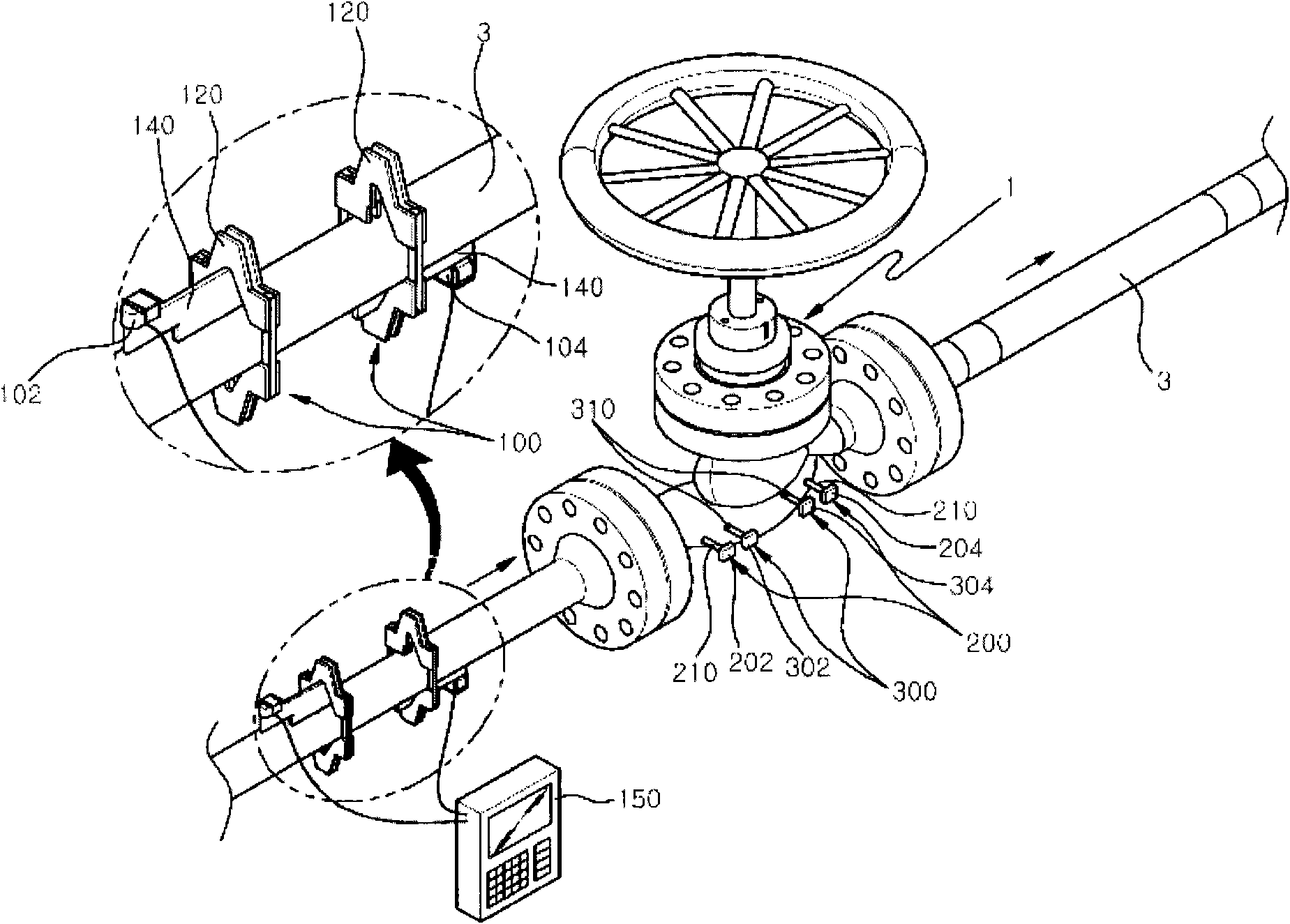
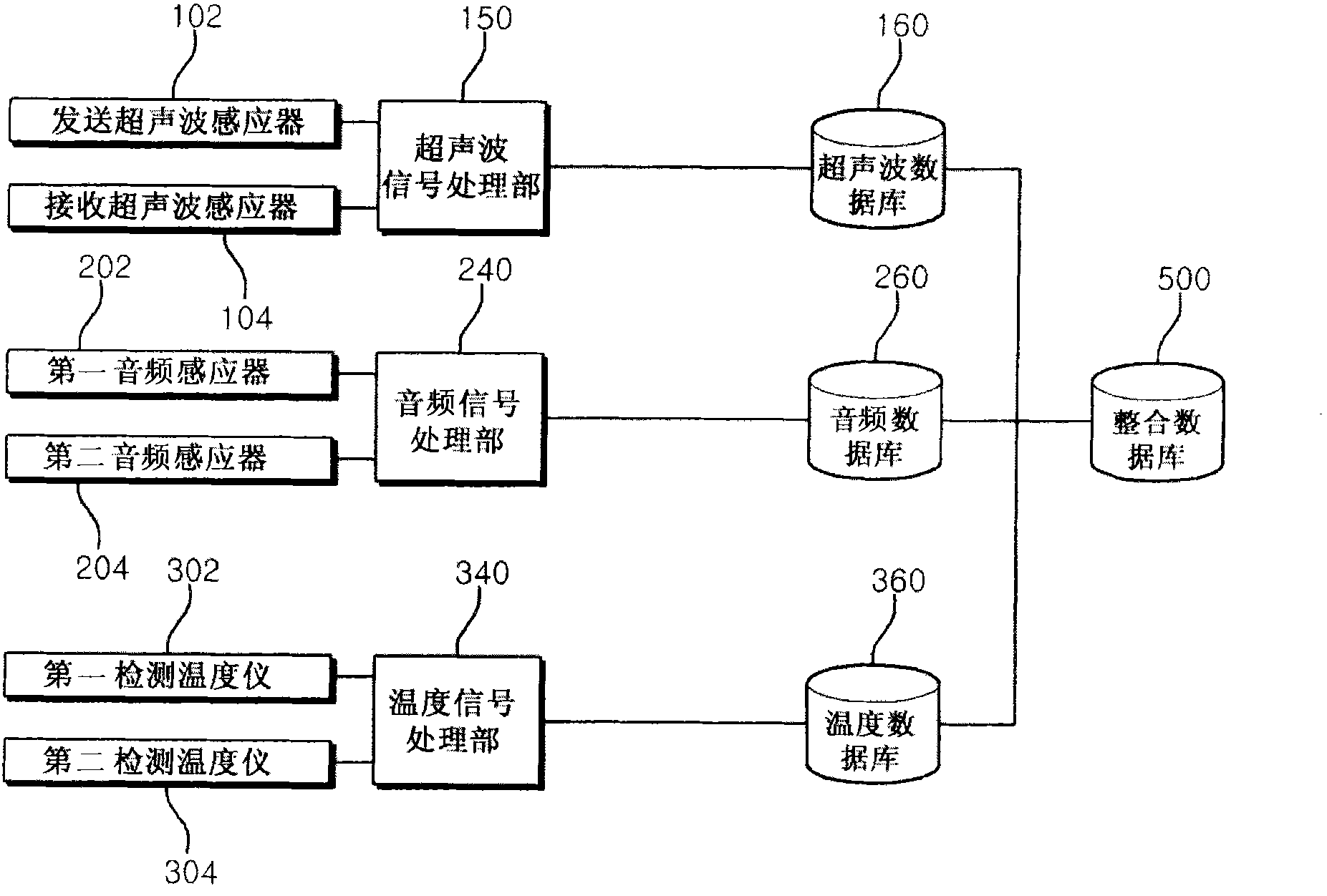
[0039] figure 1 is an oblique view showing pipes and pipelines arranged with the device for detecting fluid leakage of the present invention, figure 2 is an oblique view showing a large cylinder used in the present invention, image 3 is a block diagram showing the device for detecting fluid leakage of the present invention. Such as figure 1 an...


PUM


Abstract

The present invention relates to an apparatus for detecting the leakage of fluid flowing inside a pipe or a valve in a quick and accurate manner using ultrasonic wave, sound, and temperature variations, and to a method for measuring fluid leakage using same. To this end, the apparatus of the present invention comprises: ultrasonic leakage measuring means arranged at a valve and at the entrance ofa fluid inlet pipe from among the pipes connected to the valve to measure the leakage of fluid from the valve through the use of ultrasonic waves; sound leakage measuring means arranged at the fluid inlet side and the fluid outlet side of the valve body to measure the leakage of fluid from the valve through acoustic signals; and temperature leakage measuring means arranged at the fluid inlet sideand the fluid outlet side of the valve body to measure variations in the temperature of the valve. The present invention accurately measures a relatively low rate of fluid leakage from the valve or pipe by using ultrasonic waves, acoustic signals, and temperature variations. Further, leakage rate data obtained from the measurement can be quantized and compared with a valve under the same conditions to check the leakage rate in an easy and quick manner. In addition, fluid leakage can be accurately measured even in the event the fluid leakage rate of the valve or pipe is relatively high.

Description

technical field [0001] The invention relates to a device for detecting pipeline fluid leakage based on ultrasonic waves, audio frequency and temperature difference and a fluid leakage detection method using the device, in particular to a device based on ultrasonic, A device for detecting pipeline fluid leakage by audio frequency and temperature difference and a method for detecting fluid leakage using the device. Background technique [0002] Typically, industrial equipment such as power stations and chemical plants use tens of thousands of pipes. Among them, the pipelines that have a great impact on the safe operation of the equipment are undergoing operation safety inspections and internal leakage inspections of the pipelines. [0003] Due to the insertion of foreign matter into the sealing surface of the pipe seat, frequent opening or closing of the pipe and damage to the internal parts of the pipe, cracks in the pipe body and pipe seat, defects in the liner of the pipe ...

Claims


Application Information

Patent Timeline
IPC IPC(8): G01N29/02
CPCG01N29/326G01N29/14G01M3/24G01M3/002G01M3/00G01N29/00G01N29/02
Inventor 金永范崔钟贵
Owner 韩国电力系统开发设计有限公司
Learn More