Heat radiation system

A technology of heat dissipation system and hot air duct, applied in the field of machinery, can solve the problems of large temperature gradient and affect the heat dissipation of network equipment in the cabinet, and achieve the effect of improving cooling efficiency and good heat dissipation

Active Publication Date: 2012-09-19
XFUSION DIGITAL TECH CO LTD
View PDF0 Cites 0 Cited by
  • Summary
  • Abstract
  • Description
  • Claims
  • Application Information

AI Technical Summary

Problems solved by technology

[0005] Due to the influence of the local mixed flow area, the temperature in the air intake area of ​​the cabinet increases, and in the vertical direction of the cabinet (such as figure 2 The temperature gradient in the arrow direction) is large, which affects the heat dissipation of the network equipment in the cabinet

Method used


Image

  • Heat radiation system
  • Heat radiation system
  • Heat radiation system

Examples


Embodiment Construction

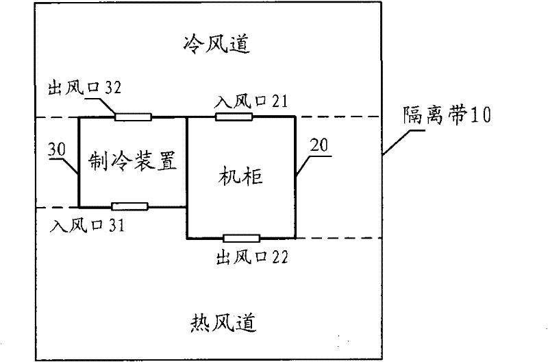
[0021] An embodiment of the present invention provides a cooling system, image 3 A top view of the heat dissipation system is shown, which includes: an isolation strip 10 for separating the cold air passage from the hot air passage; the isolation strip includes: a cabinet 20 and a refrigeration device 30,

[0022] Wherein, the cooling device 30 has an air outlet 32 ​​on the side facing the cold air passage, and the cabinet 20 has an air inlet 21 on the side facing the cold air passage; The air inlet 21 enters; the side of the refrigeration device 30 facing the hot air passage has an air inlet 31, and the side of the cabinet 20 facing the hot air passage has an air outlet 22; the hot air discharged from the air outlet 22 of the cabinet 20 passes through the hot air passage Enter from the air inlet 31 of the refrigeration device 30 .

[0023] In the heat dissipation system in the embodiment of the present invention, there is an isolation zone for separating the cold air duct a...


PUM


Abstract

The embodiment of the invention provides a heat radiation system. The system comprises an isolation belt which is used for isolating a cold air channel from a hot air channel, wherein the isolation strip comprises a cabinet and a refrigerating device; one side, facing the cold air channel, of the refrigerating device is provided with an air outlet; one side, facing the cold air channel, of the cabinet is provided with an air inlet; cold air exhausted from the air outlet of the refrigerating device enters from the air inlet of the cabinet through the cold air channel; one side, facing the hot air channel, of the refrigerating device is provided with the air inlet; one side, facing the hot air channel, of the cabinet is provided with the air outlet; and hot air exhausted from the air outletof the cabinet enters from the air inlet of the refrigerating device. By using the heat radiation device provided by the embodiment of the invention, the cold air channel is completely isolated from the hot air channel so that the cabinet can radiate very well.

Description

technical field [0001] The invention relates to the technical field of machinery, in particular to a cooling system. Background technique [0002] In the early air duct design of the container, the cold air duct and the hot air duct were not isolated, which would cause the mixing of cold air and hot air, reducing the cooling efficiency of the air conditioner in the container. The air duct design is far from meeting the heat dissipation requirements of the cabinet. [0003] The prior art provides a design method for the air duct in the container. The air conditioner is installed on the roof of the container. The air conditioner blows the cold air to the front of the cabinet, and the hot air in the cabinet is discharged from the rear of the cabinet and sucked in from the air inlets on both sides of the air conditioner. figure 1 as shown, figure 1 The direction of the cold wind and the direction of the hot wind under ideal conditions are shown, wherein, the hollow arrows repr...

Claims


Application Information

Patent Timeline
Patent Type & Authority Patents(China)
IPC IPC(8): H05K7/20
Inventor 曲中江
Owner XFUSION DIGITAL TECH CO LTD
Why Eureka
Try Eureka