
Yoke structure of stepping motor

A technology of stepping motor and yoke structure, applied in the direction of magnetic circuit shape/style/structure, electrical components, electromechanical devices, etc., can solve problems such as cost reduction, achieve cost reduction, stable quality, and reduce maintenance and management costs

Active Publication Date: 2011-01-26
MOATECH
View PDF3 Cites 0 Cited by
  • Summary
  • Abstract
  • Description
  • Claims
  • Application Information

AI Technical Summary

Problems solved by technology

[0009] According to the yoke structure of the stepping motor of the present invention, in order to solve the problem of the directionality of the yoke teeth when laminating the yoke of the stepping motor, the structure of the yoke is changed from the existing guide structure assembled in one direction to a multi-directional Assembled guide structure, so that the original layered two yokes are changed to one type of yoke, and the angle of the yoke teeth will not be affected during the layering, and only one type of yoke is needed, so only one type of mold is required, Thereby reducing the maintenance and management cost of the mold, achieving cost reduction, and at the same time ensuring stable quality

Method used

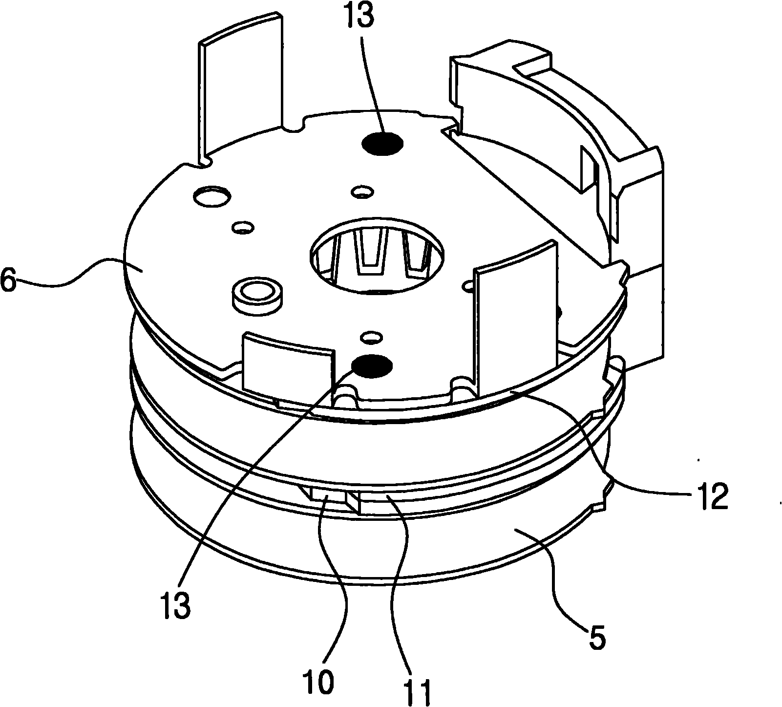

Image

  • Yoke structure of stepping motor
  • Yoke structure of stepping motor
  • Yoke structure of stepping motor

Examples


Embodiment Construction

[0014] Hereinafter, embodiments of the present invention will be described with reference to the drawings.

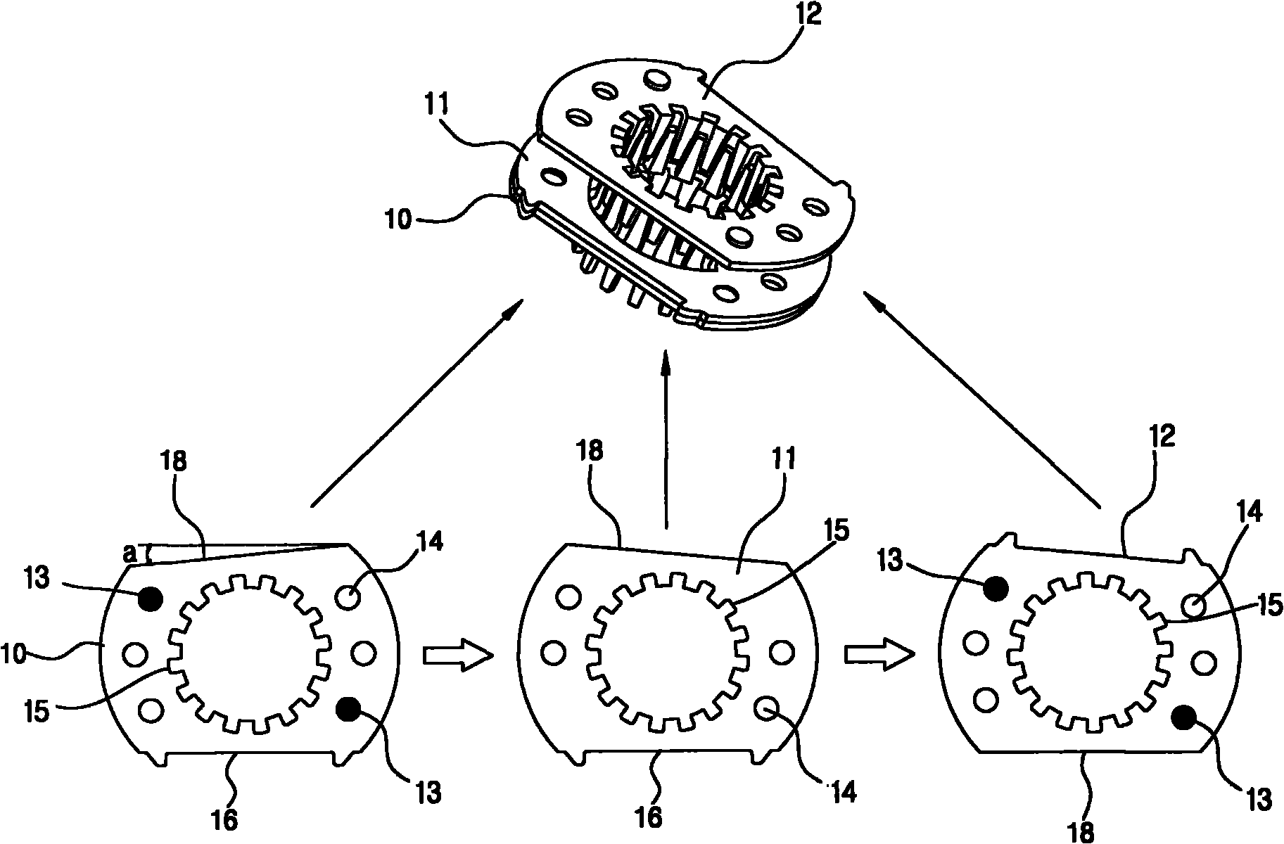
[0015] Such as figure 2 and image 3 As shown, the yoke 10, the yoke 11 and the yoke 12 are the same yoke, and the yoke 10, the yoke 11 and the yoke 12 respectively include: a lower cut-off part 16, an upper guide part 18 inclined at a°, a central gear tooth 15, and a The gear teeth 15 are spaced apart by a plurality of through holes 14 and protrusions 13 at a set distance. In the figure, two through holes 14 and one protruding portion 13 form a group, and two groups are provided on both sides, forming a symmetrical relationship. Since the yoke 11 is shown on the back side, the protrusion 13 cannot be seen.

[0016] The a° inclination angle of the upper guide portion 18 is the step angle of the motor. For example, when the motor rotates at a step angle of 7.5°, the tilt angle of a° is 7.5°, and when the motor rotates at a step angle of 15°, the tilt angle of a° is ...


PUM


Abstract

The invention relates to a yoke structure of a stepping motor. The yoke comprises a lower truncation part, an upper guide part inclining for alpha degrees, central gear teeth, a plurality of through holes apart from the gear teeth in set distance, and a projecting part; and the yoke structure can be laminated by using one kind of yoke.

Description

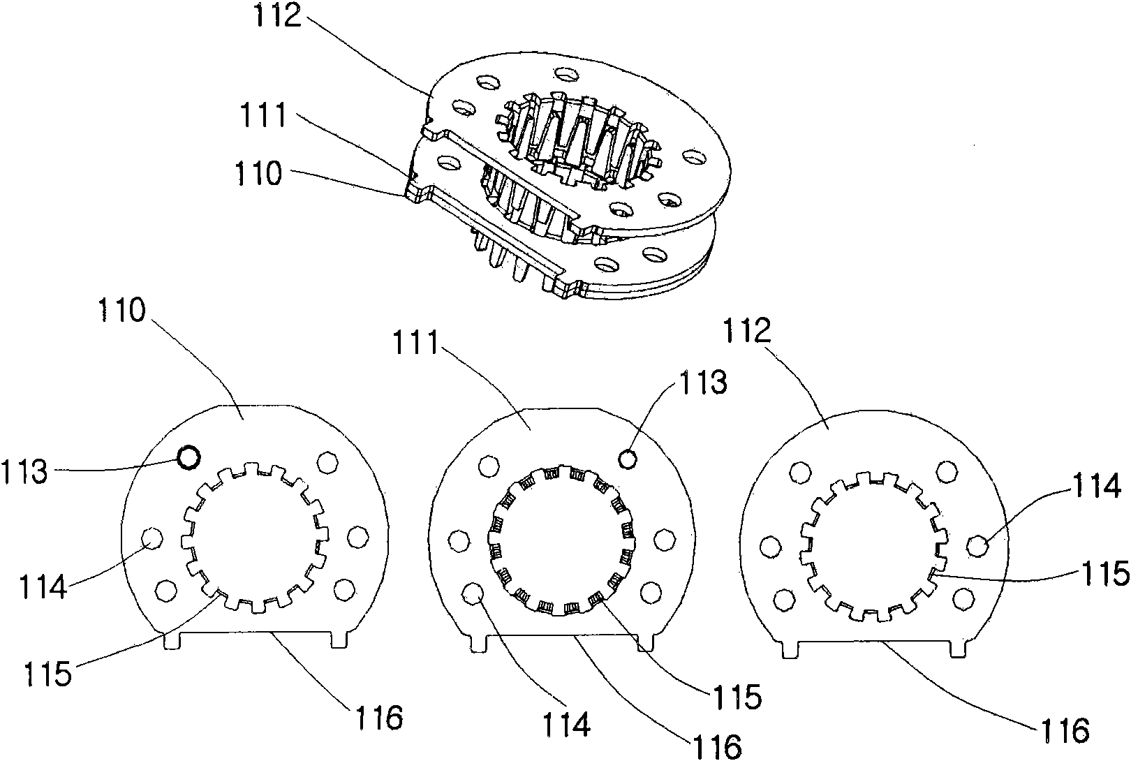
technical field [0001] The present invention relates to a yoke structure of a stepping motor, in particular to a yoke structure of a stepping motor which can be laminated with one kind of yoke. Background technique [0002] Such as figure 1 As shown, among the yoke 110 , the yoke 111 and the yoke 112 , the yoke 110 and the yoke 111 are the same kind of yoke, and the angle direction formed by the gear teeth of the remaining yoke 112 is different from that of the yoke 110 and the yoke 111 . [0003] Each of the yokes 110 , 111 and 112 includes a lower cutout portion 116 , a central tooth 115 , and a through hole 114 and a protrusion 113 spaced apart from the tooth 115 by a set distance. [0004] The gear teeth 115 of the yoke 110 face downward; the yoke 111 is combined with the back of the yoke 110 , and the gear teeth 115 face upward; the gear teeth 115 of the yoke 112 face downward. [0005] Therefore, the gear teeth 115 of the yoke 111 and the gear teeth 115 of the yoke 1...

Claims


Application Information

Patent Timeline
Patent Type & Authority Applications(China)
IPC IPC(8): H02K37/00H02K1/12
CPCH02K37/02
Inventor 朴埈建
Owner MOATECH
Learn More