
Method and device for realizing state machine

An implementation method and state machine technology, applied in the direction of program control devices, etc., can solve problems such as low efficiency, complicated state machine maintenance process, and complicated maintenance process

Inactive Publication Date: 2011-01-26
RUIJIE NETWORKS CO LTD
View PDF8 Cites 46 Cited by
  • Summary
  • Abstract
  • Description
  • Claims
  • Application Information

AI Technical Summary

Problems solved by technology

This method can implement the state machine more intuitively, but when using this method to implement the state machine, since the action is designed for a specific state and event, an action may be mixed with different logic processing, so the efficiency of the state machine conversion is very low. In addition, the number of events (events) must be numbered consecutively starting from 0. Therefore, if an event is added in a certain state, even if other states do not need to consider this event, corresponding processing needs to be added to ensure the integrity of the matrix. Therefore , the maintenance process of the state machine is very complicated, especially when the system is very complex, the state machine is not even maintainable
[0011] In summary, the state machine implemented by the existing technology has low efficiency in controlling each state of the state machine, and the maintenance process is complicated

Method used


Image

  • Method and device for realizing state machine
  • Method and device for realizing state machine
  • Method and device for realizing state machine

Examples


Embodiment Construction

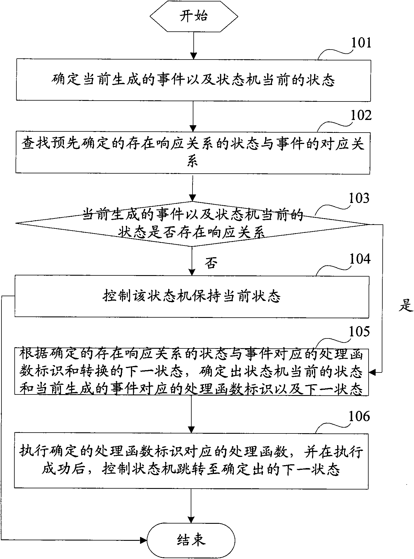
[0044] In order to provide an implementation plan for improving the control efficiency of each state of the state machine and easy maintenance, the embodiment of the present invention provides a method and device for realizing the state machine. The preferred embodiment of the present invention will be described below in conjunction with the accompanying drawings. It should be understood that , the preferred embodiments described here are only used to illustrate and explain the present invention, not to limit the present invention. And in the case of no conflict, the embodiments in the present application and the features in the embodiments can be combined with each other.

[0045] According to an embodiment of the present invention, a method for implementing a state machine is firstly provided. The method is implemented based on predetermined control information, wherein the predetermined control information includes: a corresponding relationship between a state with a respons...


PUM


Abstract

The invention discloses a method and a device for realizing a state machine. The main technical scheme of the method comprises the following steps of: determining the currently generated event and the current state of the state machine; searching a corresponding relationship between a predetermined state and a predetermined event with a response relationship and judging whether the response relationship exists between the currently generated event and the current state of the state machine or not; if the response relationship exists between the currently generated event and the current state of the state machine, determining a processing function identifier and a switched next state corresponding to the current state of the state machine and the currently generated event according to a processing function identifier and a switched next state corresponding to the predetermined state and the predetermined event with the response relationship, and controlling the state machine to jump tothe determined next state after a processing function corresponding to the determined processing function identifier is successfully executed; and if the response relationship does not exist between the currently generated event and the current state of the state machine, controlling the state machine to keep the current state. The state machine is realized by the technical scheme; state switching efficiency is improved; and easy maintenance is achieved.

Description

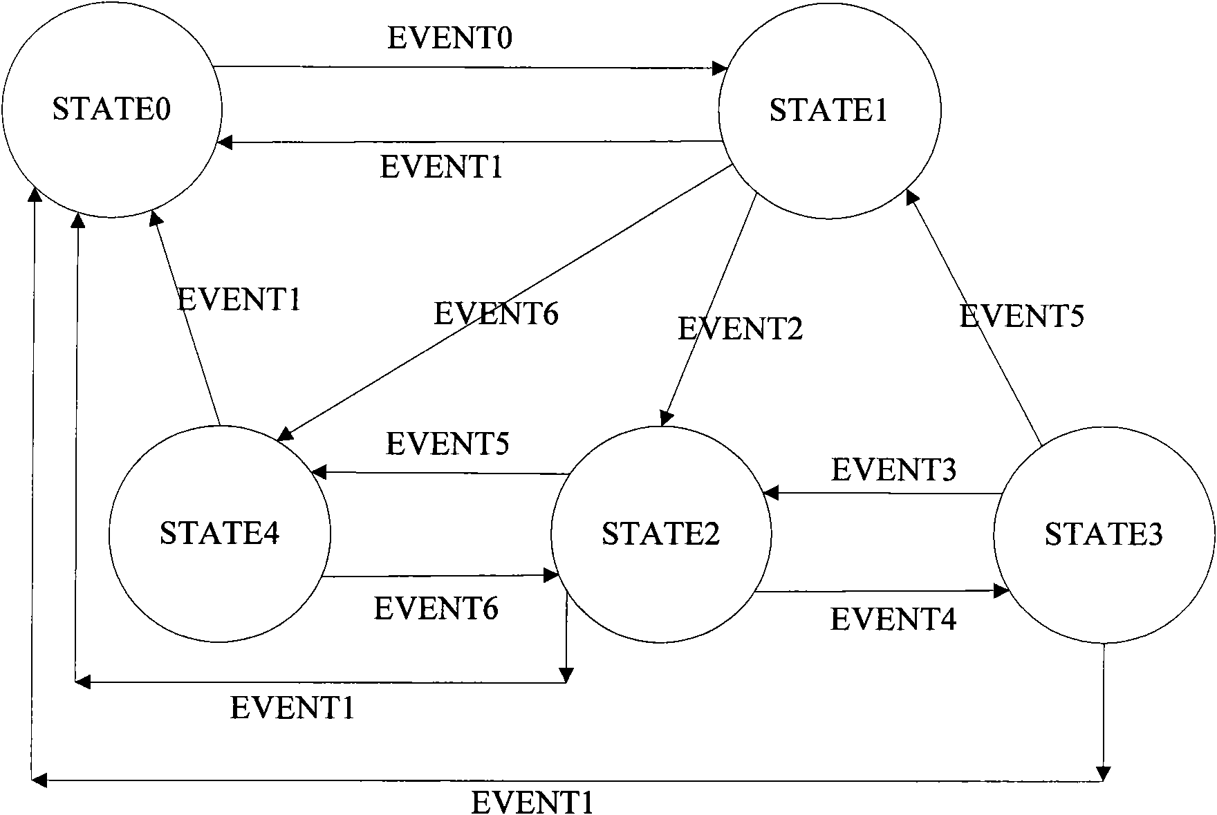
technical field [0001] The invention relates to the technical field of state machines, in particular to a method and device for realizing a state machine. Background technique [0002] A finite state machine (Finite State Machine, FSM) is also called a finite state automaton or simply a state machine, which represents a mathematical model of a finite number of states and transitions and actions between these states. In general, a finite state machine controls state transitions through the relationship between states, events, transitions, and actions, where: [0003] State (State) refers to a state of an object in its life cycle. An object in a certain state must meet certain conditions, perform certain actions, or wait for certain events; [0004] Event (Event) refers to those things that occupy a certain position in time and space and are meaningful to the state machine, that is, events usually cause state changes, prompting the state machine to switch from one state to an...

Claims


Application Information

Patent Timeline
Patent Type & Authority Applications(China)
IPC IPC(8): G06F9/44
Inventor 熊俊
Owner RUIJIE NETWORKS CO LTD
Learn More