
Device, system and method for obtaining vital sign information of a subject

Inactive Publication Date: 2018-10-04
KONINKLJIJKE PHILIPS NV
View PDF7 Cites 32 Cited by
  • Summary
  • Abstract
  • Description
  • Claims
  • Application Information

AI Technical Summary

Benefits of technology

The patent text describes a system and method for extracting heart rate using wearable devices. To improve accuracy, the system uses prior information about expected heart rate changes based on factors like altitude, temperature, and activity level. The system also takes into account changes in these factors to control the settings of the heart rate extraction unit. Overall, the technology aims to increase heart rate detection accuracy and improve control of the system parameters for improved reliability and personalization.

Problems solved by technology

Both, the HR and the RR are still difficult to measure without having direct body contact.
However, these obtrusive methods are uncomfortable and unpleasant for the patient being observed.
Moreover, unobtrusive respiratory rate measurements can be accomplished optically by use of a stationary video camera.
Further, one or more video cameras are used for unobtrusively monitoring the HR, the RR or other vital signs of a subject by use of remote photoplethysmographic imaging.
Moreover, unobtrusive non-camera based systems for obtaining vital sign information are also known.
One of the key challenges in such devices and method is to enable the determination of vital signs, in particular of the heart rate, reliably and accurately over the whole range of the heart rate spectrum, which is approximately from 30 to 240 bpm.
In general this is a common problem of applications that try to monitor heart rate.

Method used


Image

  • Device, system and method for obtaining vital sign information of a subject
  • Device, system and method for obtaining vital sign information of a subject
  • Device, system and method for obtaining vital sign information of a subject

Examples


second embodiment

[0061]The camera-based respiration monitoring as used in the above described second embodiment of the system and method is generally realized by measuring the subtle breathing motion in the subject's chest (or belly) area. Thus, it critically depends on the detection of subtle breathing motion in the image data. The motion-based respiratory signal monitoring is not always reliable, due to the difficulty of breathing motion detection in certain cases. For example, a neonate in the NICU sometimes has shallow breathing, where it is challenging to detect the very subtle breathing motion. If the algorithm parameters are adjusted to be sensitive enough to the very subtle motion of shallow breathing, another problem will arise: the algorithm may not be able to differentiate the subtle breathing motion from the noises (illumination, camera, etc.). For instance, pointing to the wall, the algorithm can produce the respiration-like signal due to the noises.

third embodiment

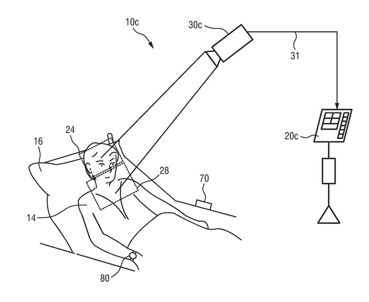
[0062]Hence, in the system 10b and the device 20b illustrated in FIGS. 4 and 5 a separate detection unit 40b is provided for acquiring detection data 41 allowing the extraction of the subject's respiration rate or representing the subject's respiration rate in addition to the imaging unit 30b for acquiring image data 31 from a skin portion 17 of the subject 14, e.g. from the face, allowing the extraction of the subject's heart rate. The detection unit 40b may e.g. comprise a plurality of unobtrusive sensors 42 embedded into the bed, e.g. in the mattress. Such sensors 42 may e.g. include pressure sensors measuring a signal representative of body motion of the subject's body, e.g. of the chest wall, caused by the respiratory movements. It is to be understood that the sensors 42 can also be integrated into a textile structure of the bed, such as the blanket or the pillow, or into textiles worn by the subject 14. The respiration rate can thus be derived from the absolute pressure or pre...

fifth embodiment

[0076]In still another embodiment, the control of the HR extraction may be personalized to the subject 14. Personalization may e.g. be achieved by receiving identity data of the subject 14 as input or by recognizing the subject 14 from the image data 31 by use of a recognition unit 27, e.g. a face recognition unit, as conventionally known. This is illustrated in the device 20d illustrated in FIG. 8. The expected changes in the HR can thus be personalized, and the system parameters can be changed accordingly. For example, if it known (from prior data, e.g. stored in a storage unit in the device, in the system or e.g. in a hospital archive) that for person A, 10° C. increase in temperature results in 40 bpm increase in HR, versus person B for whom only 10 bpm increase happens for 10° C. increase in temperature, the system parameters can be changed differently for person A and person B. The same is true for the other factors that influence HR, such as respiration, activity, altitude, s...


PUM


Abstract

The present invention relates to device, system and method for obtaining vital sign information of a subject (14). To enable reliably obtaining vital sign information of a subject, in particular of the subject's heart rate, the proposed device comprises an input unit (21) for obtaining a set of image data (31) detected from a skin portion (24) of the subject (14) allowing the extraction of the subject's heart rate (51) and a set of detection data (31, 41) detected from a body portion of the subject (14) allowing the extraction of the subject's respiration rate (53) or representing the subject's respiration rate (53), a heart rate extraction unit (22) for extracting the subject's heart rate from said set of image data (31) by use of photoplethysmography, a prediction unit (23) for predicting changes of the subject's heart rate based on the subject's respiration rate extracted from or represented by said set of detection data, and a control unit (24) for controlling one or more settings of said heart rate extraction unit (22) based on the predicted changes of the subject's heart rate.

Description

FIELD OF THE INVENTION[0001]The present invention relates to a device, system and method for obtaining vital sign information, in particular the heart rate, of a subject, such as person or animal.BACKGROUND OF THE INVENTION[0002]Vital signs of a person, for example the heart rate (HR) or respiratory information (respiratory parameters) such as the respiratory rate (RR), can serve as a powerful predictor of serious medical events. For this reason the respiratory rate and / or the heart rate are often monitored online in intensive care units or in daily spot checks in the general ward of a hospital. Besides the heart rate, the respiratory rate is one of the most important vital signs. Both, the HR and the RR are still difficult to measure without having direct body contact. In present intensive care units, thorax impedance plethysmography or the respiratory inductive plethysmography are still the methods of choice for measuring the RR, wherein typically two breathing bands are used in o...

Claims


Application Information

Patent Timeline
IPC IPC(8): A61B5/0205A61B5/00
CPCA61B5/0205A61B5/7275A61B5/7221A61B5/02427A61B5/0816A61B5/0537A61B5/1118A61B5/1116A61B2560/0252A61B2560/0247A61B5/02433A61B5/7292A61B5/0077A61B5/02416
Inventor BULUT, MURTAZA
Owner KONINKLJIJKE PHILIPS NV
Learn More