
LDO constant voltage control circuit

A voltage-stabilizing circuit and voltage-dividing resistor technology, applied in the direction of adjusting electrical variables, control/regulating systems, instruments, etc., can solve the problems of loop instability, poor LDO system stability, large open-loop gain, etc., and achieve frequency compensation. The effect of convenience, good load regulation, and high power supply rejection ratio

Active Publication Date: 2011-01-26
SHENZHEN FM ELECTRONICS GRP CO LTD
View PDF4 Cites 13 Cited by
  • Summary
  • Abstract
  • Description
  • Claims
  • Application Information

AI Technical Summary

Problems solved by technology

[0004] In order to solve the above-mentioned problems of large open-loop gain, unstable loop, and poor stability of the LDO system with small open-loop gain, the present invention provides an LDO voltage stabilizing circuit

Method used


Image

  • LDO constant voltage control circuit
  • LDO constant voltage control circuit
  • LDO constant voltage control circuit

Examples


Embodiment 1

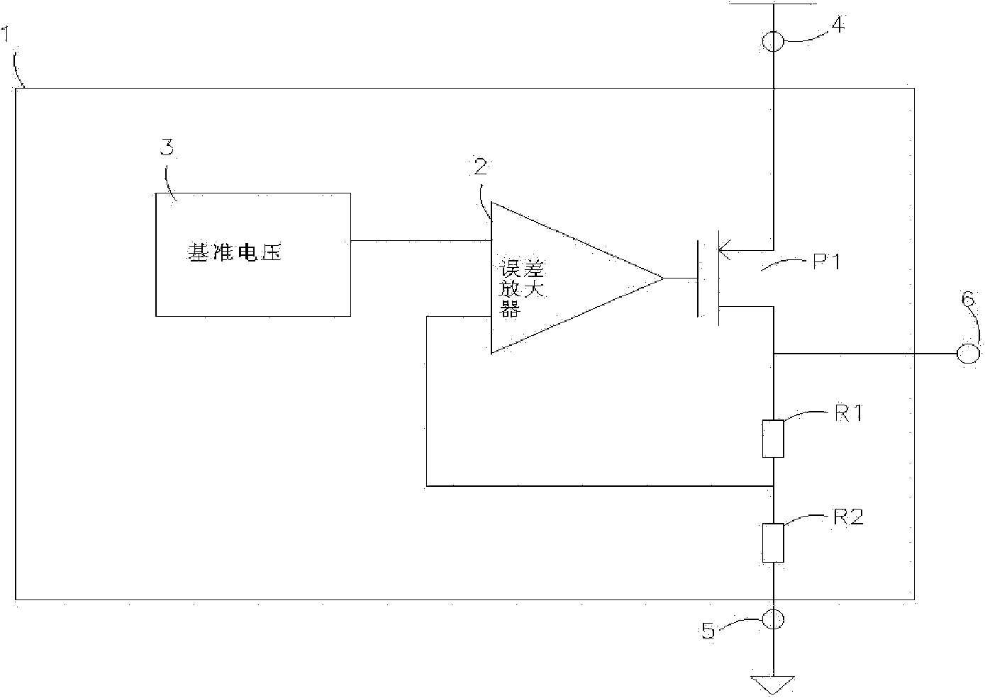
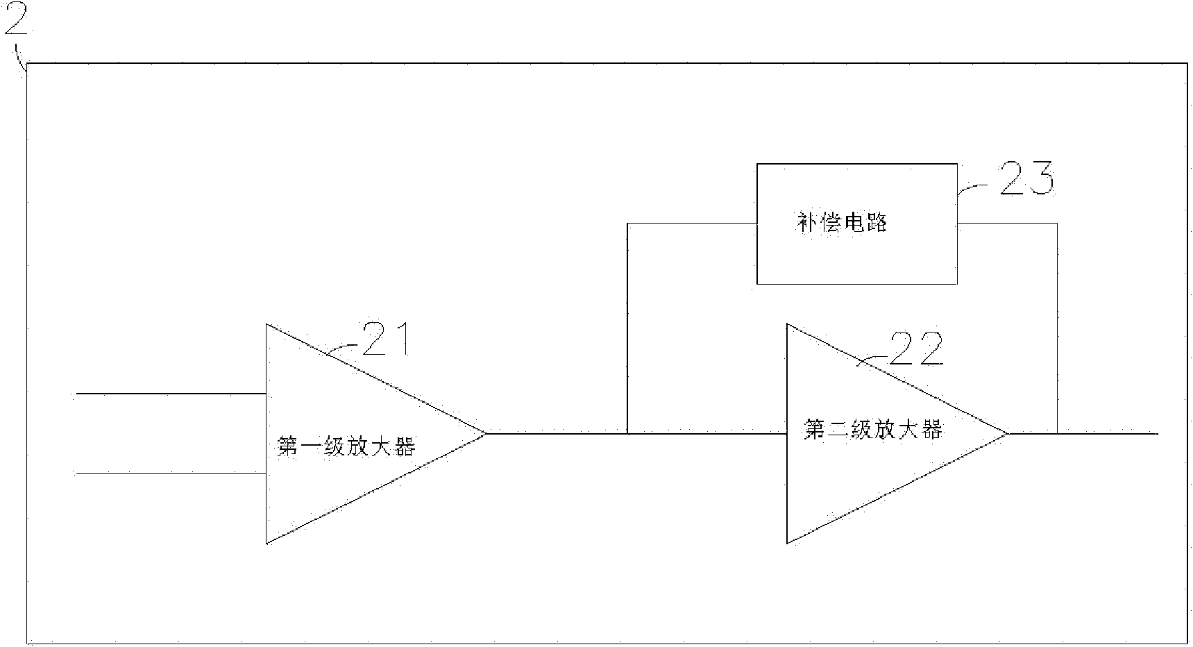
[0019] combine figure 1 , figure 2 , an LDO voltage stabilizing circuit, including a reference voltage module 3 and an error amplifier module 2, a driving tube P1, a voltage dividing resistor R1 and a voltage dividing resistor R2, and the error amplifier module 2 includes a first-stage amplifier 21, a second A stage amplifier 22 and a compensation circuit 23, the compensation circuit 23 is connected in parallel with the second stage amplifier 22, and the first stage amplifier 21 is connected in series with the parallel circuit of the compensation circuit 23 and the second stage amplifier 22. Both the first-stage amplifier and the second-stage amplifier are high-gain amplifiers.

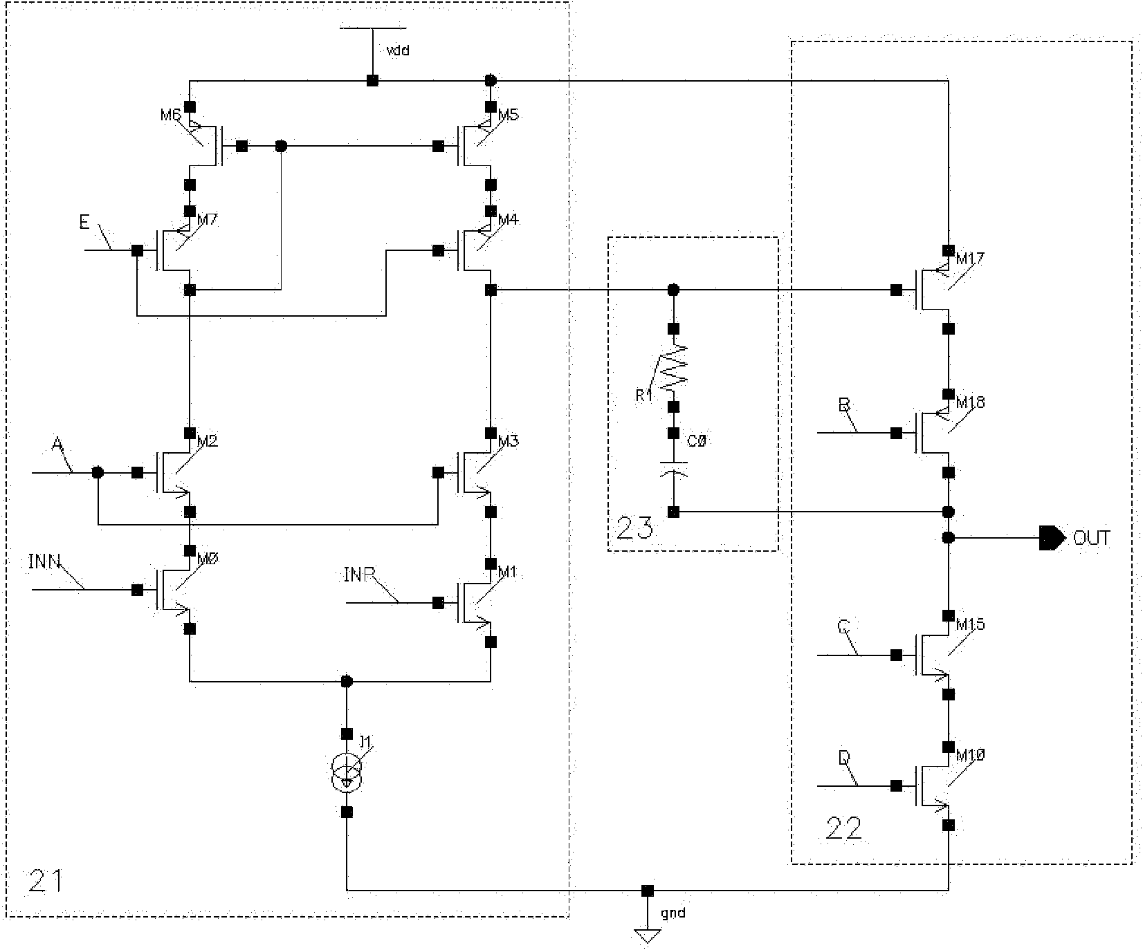
[0020] combine image 3 , which is a circuit diagram of the present invention, the first-stage amplifier 21 includes MOS transistors M0, MOS transistors M1, MOS transistors M2, MOS transistors M3, MOS transistors M4, MOS transistors M5, MOS transistors M6 and MOS transistors M7, constant current S...


PUM


Abstract

The invention provides a low dropout (LDO) constant voltage control circuit, which belongs to the field of semiconductor integrated circuits. For the problem of poor overall performance of an LDO system which has large open loop gain, unstable loop and small open loop gain in the prior art, the LDO constant voltage control circuit comprises a reference voltage module, an error amplifier module, a driving tube P1, a divider resistor R1 and a divider resistor R2, wherein the error amplifier module comprises a first-stage amplifier, a second-class amplifier and a second-class amplifier and a compensation circuit which is connected with the second-class amplifier in parallel; and the first-class amplifier is connected with the parallel circuit of the compensation circuit and the second-class amplifier in series. The LDO constant voltage control circuit is applied to portable electronic equipment.

Description

technical field [0001] The invention relates to a semiconductor integrated circuit, in particular to an LDO voltage stabilizing circuit. Background technique [0002] LDO (Low Dropout Regulator) regulated power supplies are used in many electronic devices. LDO regulated voltage circuits have outstanding advantages in applications such as simple structure, low cost, low noise, low power consumption, and small package size. widely used in electronic equipment. [0003] Such as figure 1 As shown in , the basic frame structure of the existing LDO circuit is composed of a reference voltage module 3 and an error amplifier module 2, a driving tube, and voltage dividing resistors R1 and R2. The reference voltage module 3 generates a reference voltage that has nothing to do with the input power supply voltage 4 and temperature. The voltage dividing resistor samples the output voltage 6 signal. The error amplifier will compare the resistance R1, R2 divided voltage and the size of th...

Claims


Application Information

Patent Timeline
IPC IPC(8): G05F1/56
Inventor 袁川
Owner SHENZHEN FM ELECTRONICS GRP CO LTD
Learn More