Waste oil guiding and collecting device in wellhead area

A collection device and oil pollution technology, which is applied in the direction of wellbore/well components, earthwork drilling and production, etc., can solve the problem of being unable to prevent oil pollution from flowing down, and achieve the effects of convenient dismantling, safety assurance, and strong versatility

Active Publication Date: 2013-03-27
CNOOC ENERGY TECH & SERVICES +1
View PDF5 Cites 0 Cited by
  • Summary
  • Abstract
  • Description
  • Claims
  • Application Information

AI Technical Summary

Problems solved by technology

Since there is a gap between the two, it will not be able to prevent the oil from flowing down the outer wall of the riser

Method used


Image

  • Waste oil guiding and collecting device in wellhead area
  • Waste oil guiding and collecting device in wellhead area

Examples


Embodiment Construction

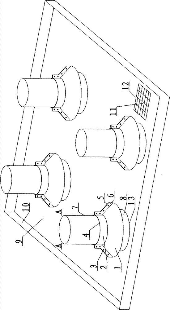
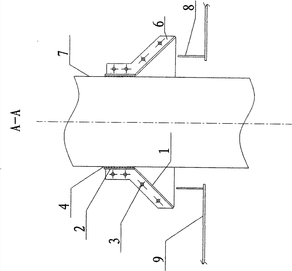
[0014] 1. Laying of impermeable steel plate 9. Firstly, remove the grid plate originally laid in the wellhead area of ​​the platform, and then lay steel plates of appropriate size and weld them together. An annular baffle plate is welded around the waterproof casing 7 and a coaming plate 10 is welded around the wellhead area, and the height of the two is 100-200mm. Set up an oil stain collection tank 11 at a suitable position in the wellhead area, and cover the top of the collection tank 11 with a grid plate 12 to ensure that the oil dirt can flow into the collection tank 11 smoothly, and ensure the safety of the operator and prevent other items from falling into the collection tank 11 in.

[0015] 2. Production of horn-shaped sleeves. The lower cone 1 and the upper cylinder 2 are rolled into two symmetrical half tiles. The inner side of the connection between the lower cone 1 and the upper cylinder 2 forms a natural cut, so the inner side is welded according to the single c...


PUM


Abstract

The invention discloses a waste oil guiding and collecting device in a wellhead area, which consists of a conductor tube, a lower cone, an upper cylinder, half tiles, bolts, a rubber gasket, a stainless steel plate, an annular baffle, enclosing plates, a waste oil collection groove and a plate grid, wherein the conductor tube is provided with a horn-shaped sleeve; and waste oil on the surface of the horn-shaped sleeve is guided onto the steel plates, and then is recycled and treated by the waste oil collection groove. The waste oil guiding and collecting device can smoothly guide and collect the waste oil produced in workover treatment, and reduces risks in the field operation.

Description

technical field [0001] The invention belongs to an oil pollution diversion collection device in a wellhead area. Background technique [0002] At present, the decks laid in the wellhead area of ​​offshore oil platforms in service in China are all gratings, which is because the gratings are non-slip, light in weight, and do not need to be fired during installation. However, as people pay more attention to marine environmental protection, the problems arising from it cannot be ignored more and more. The main problem is that the oil generated during workover operations directly drips onto the sea surface or flows down the outer wall of the riser casing through the beams in the middle of the grid plate, causing serious pollution to the marine environment. In order to solve this problem, and considering the economy and convenience, it is better to replace the grid plate in the wellhead area of ​​the platform with an impermeable steel plate. However, since there may be a large a...

Claims


Application Information

Patent Timeline
Patent Type & Authority Patents(China)
IPC IPC(8): E21B41/00
Inventor 彭绍源尹彦坤邓欣钟俊锋邓秀铭
Owner CNOOC ENERGY TECH & SERVICES
Why Eureka
Try Eureka