
Numerical-control direct-drive turning-milling composite rotary working table

A technology of rotary table and turntable, which is applied in the direction of manufacturing tools, metal processing equipment, metal processing machinery parts, etc., can solve the problem of insufficient rotation speed, and achieve the effect of improving efficiency, saving energy and materials, and high surface quality

Inactive Publication Date: 2011-01-26
烟台环球机床附件集团有限公司
View PDF6 Cites 26 Cited by
  • Summary
  • Abstract
  • Description
  • Claims
  • Application Information

AI Technical Summary

Problems solved by technology

The speed of the CNC direct drive rotary table at the present stage cannot meet the requirements of the turning and milling compound rotary table. If you want to increase the speed, the most important thing is to increase the rated speed of the direct drive motor itself. Once the rated speed is increased, the motor’s The requirements for power consumption, heat dissipation, turntable bearing components, rotary sealing components and other aspects have also increased accordingly

Method used


Image

  • Numerical-control direct-drive turning-milling composite rotary working table
  • Numerical-control direct-drive turning-milling composite rotary working table
  • Numerical-control direct-drive turning-milling composite rotary working table

Examples


Embodiment Construction

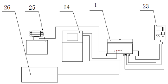
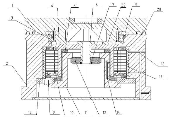
[0034] In the following, the present invention will be further described by using the following embodiments in conjunction with the accompanying drawings.

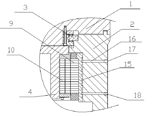
[0035] figure 2 The structure of the present invention is shown in , above is a disc-shaped working turntable 1, the lower end surface of the working turntable 1 is provided with a rotating shaft 22, the rotating shaft 22 is perpendicular to the upper and lower end surfaces of the working turntable 1, and the bottom of the working turntable 1 is the turntable base 2. A hollow circular cavity matched with the rotating shaft 22 is provided in the middle, and the lower end surface of the working turntable 1 is placed on the upper end surface of the turntable base 2, and is sealed and bonded to it. Such as Figure 4 As shown, the rotating shaft 22 is provided with a bearing 3, wherein the outer ring 31 of the bearing is fixed to the inner wall of the cavity of the turntable base 2 by screws, and its inner ring 32 is fixedly ...


PUM


Abstract

The invention discloses a numerical-control direct-drive turning-milling composite rotary working table, which comprises a disc-shaped working rotary table, a hollow rotary table base and a bearing, wherein an outer ring of the bearing is fixedly connected with an inner wall of a cavity of the rotary table base; a rotating shaft of the working rotary table extends into an inner ring of the bearing; the working rotary table is fixedly connected with the inner ring; a motor stator, a motor rotor and a cylindrical hollow connecting sleeve which is used for fixing the motor rotor are also arranged in the cavity of the rotary table base; the motor stator is fixed on an inner wall of a cavity at the lower end of the rotating shaft along the axial direction of the rotating shaft; the upper end face of the connecting sleeve is fixedly connected with the lower end face of the rotating shaft; the motor rotor is fixed on an outer wall of the connecting sleeve; and a hollow part of the connecting sleeve is provided with an angle positioning device and a locking mechanism. The numerical-control direct-drive turning-milling composite rotary working table has the advantages of high efficiency, simple transmission structure and high radiating and sealing properties.

Description

technical field [0001] The invention relates to the field of numerical control machining, and more specifically relates to a numerical control direct-drive turning-milling compound rotary table with convenient operation, simple transmission mechanism and high efficiency. Background technique [0002] The equipment manufacturing industry is an important foundation for the modernization of national defense, especially the important processing equipment for high-precision and complex parts in the military industry, aviation, aerospace and other industries has long relied on imports. High-speed, high-precision and composite processing, and the maximum one-time clamping to complete the surface processing of all parts are the characteristics of this type of turn-milling composite processing machine tool. The CNC direct drive turning and milling compound rotary table is the most ideal and most important functional part of the compound processing machine tool. [0003] The CNC turn...

Claims


Application Information

Patent Timeline
IPC IPC(8): B23Q1/26
Inventor 刘毅何文曲维康刘青春王家晓
Owner 烟台环球机床附件集团有限公司
Learn More