
Wire twister

A technology of twister and twister, which is applied in auxiliary devices for rope making, textiles and papermaking, electrical components, etc. It can solve the problems of cable or rope deformation or twisting, increase cable resistance, etc., and achieve simple structure Effect

Inactive Publication Date: 2011-01-19
江阴华电新材料有限公司
View PDF5 Cites 11 Cited by
  • Summary
  • Abstract
  • Description
  • Claims
  • Application Information

AI Technical Summary

Problems solved by technology

Since the cable or rope does not produce effective plastic deformation when it passes through the wire hole or the fixed guide wheel before being twisted, the twisted multi-strand cable or rope only produces elastic deformation and / or twisting, so After the cable or rope is twisted, a recovery stress will be generated inside it, which will deform or twist the twisted cable or rope. At the same time, when the cable or rope is cut, the twisted multi-strand wire The cable or rope will immediately loosen, which will cause a lot of inconvenience to the user, and will also increase the resistance of the cable

Method used


Image

  • Wire twister
  • Wire twister
  • Wire twister

Examples


Embodiment 1

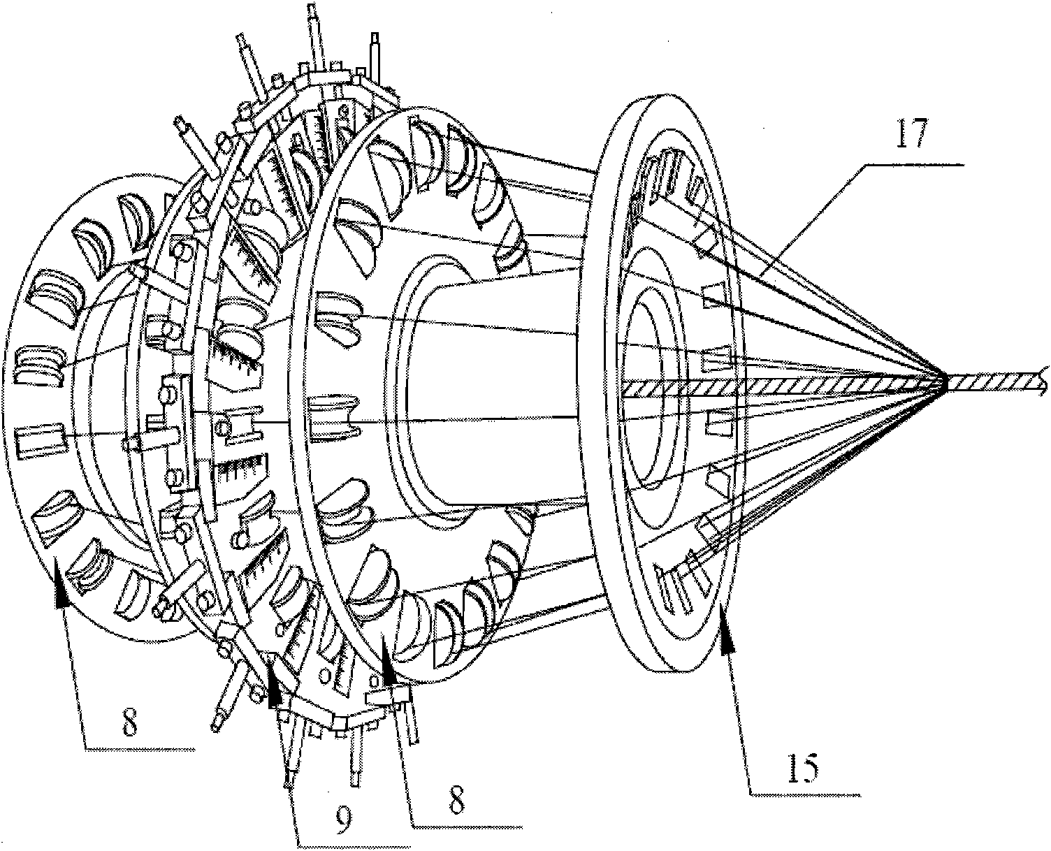
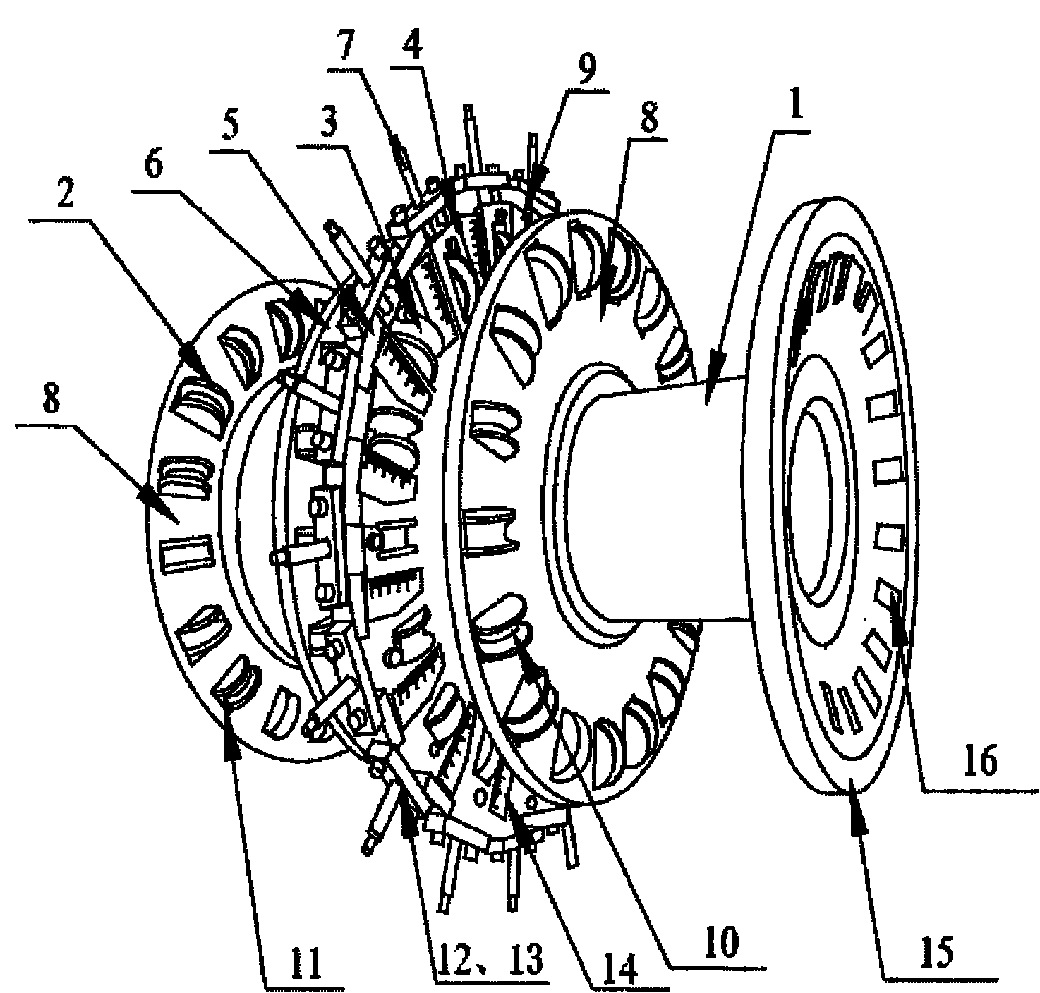
[0020] Such as figure 1 As shown, the present invention is a kind of wire twister, and this wire twister comprises 4 winch coils that are installed on the same hollow shaft 1, is provided with several wire pulleys and grooves on the concentric circumference of each strand coils hole, the guide wheel includes a fixed guide wheel 2 and a movable guide wheel 3, the fixed guide wheel 2 is connected with the winch reel through the roller on the guide wheel, and the movable guide wheel 3 passes through Described roller is connected on the slide block 4, and described slide block 4 cooperates with slide rail block 5, and one side of described slide rail block 5 is fixed on the connection plate 6, and described connection plate 6 is fixed on the hollow On the shaft 1; wherein, the axis of the roller is perpendicular to the radial line of the winch reel; an adjustment rod 7 is arranged at the end of the slider 4, and the adjustment rod 7 is arranged on the slider The adjusting parts o...

Embodiment 2

[0022] On the basis of embodiment 1, the preferred embodiment of the present invention is, because described winch includes fixed winch 8, movable winch 9 and wire passing type winch 15, described Several fixed guide wheels 2 and several movable guide wheels 3 are respectively arranged on the fixed winch reel 8 and the movable winch reel 9, and the movable winch reel 9 includes the connection disc 6, the fixed The other structures of the slide rail block 5 on the connecting plate 6 and the slide block 4 cooperating with the slide rail block 5 are exactly the same as those of the first embodiment.

Embodiment 3

[0024] On the basis of Embodiment 2, the preferred embodiment of the present invention also includes that an annular groove 10 is set on the surface of the fixed guide wheel 2 and the movable guide wheel 3, and the radial section of the annular groove 10 V-shaped, the annular groove 10 can facilitate the passage of cables, and the rest of the structure is exactly the same as that of Embodiment 2.


PUM


Abstract

The invention discloses a wire twister which comprises four twisted wire disks arranged on the same hollow shaft, wherein, the concentric periphery of each twisted wire disk is provide with a plurality of conducting wire wheels and / or slotted holes; the conducting wire wheels comprise fixed conducting wire wheels and movable conducting wire wheels, the fixed conducting wire wheels are connected with the twisted wire disks through rollers on the conducting wire wheels, and the movable conducting wire wheels are connected on a sliding block through rollers; the sliding block is matched with a sliding rail block, one side of the sliding rail block is fixed on a connecting plate, and the connecting plate is fixed on the hollow shaft; the axis of the shaft is perpendicular to the radial line of each twisted wire disk; and the end part of the sliding block is provided with an adjusting rod, and the adjusting rod adjusts the sliding block to slide along the radial direction of the connecting plate through an adjusting component arranged on the sliding rail block and / or the connecting plate. By adopting the wire twister, before cables or ropes are twisted, a plurality of the cables are plastically deformed in advance; and in addition, the cables of various specifications can be produced by adjusting the distance among the twisted wire disks and positions of the movable conducting wire wheels.

Description

technical field [0001] The invention relates to a cable production equipment, in particular to a structure of a twister. Background technique [0002] In the prior art, most cables, ropes, etc. are formed by twisting multiple strands of cables, and a twisting reel is included in the equipment for twisting cables or ropes. Existing capstans are generally only provided with some wire passing holes distributed along the circumference, or are provided with wire pulleys in the wire passing holes. Since the cable or rope does not produce effective plastic deformation when it passes through the wire hole or the fixed guide wheel before being twisted, the twisted multi-strand cable or rope only produces elastic deformation and / or twisting, so After the cable or rope is twisted, a recovery stress will be generated inside it, which will deform or twist the twisted cable or rope. At the same time, when the cable or rope is cut, the twisted multi-strand wire The cable or rope will imm...

Claims


Application Information

Patent Timeline
Patent Type & Authority Applications(China)
IPC IPC(8): H01B13/02D07B7/02
Inventor 张根华刘国洪
Owner 江阴华电新材料有限公司
Learn More