


Quick Research
Generate reliable direction feasibility study reports for your R&D in just a few steps.

Technical Q&A
Discover and master advanced knowledge NOW. Basics, ideas, possibilities, all at once.

Find Solutions
As an expert in R&D theories, this can generate solutions to your technical problems instantly.

Evaluate Feasibility
Analyze your overall solution with one click, know your potential R&D risks in advance.

Monitor Landscape
Get weekly tech updates, stay abreast of the latest tech innovations and key insights.
Multifunctional effluent faucet
A faucet, multi-functional technology, applied to multi-way valves, valve details, engine components, etc., can solve the problems of not simple and generous appearance, complicated switching operation of faucet waterway, etc., to achieve the effect of strong applicability and convenient use
- Summary
- Abstract
- Description
- Claims
- Application Information
AI Technical Summary
Problems solved by technology
Method used
Image

Examples
Embodiment 1
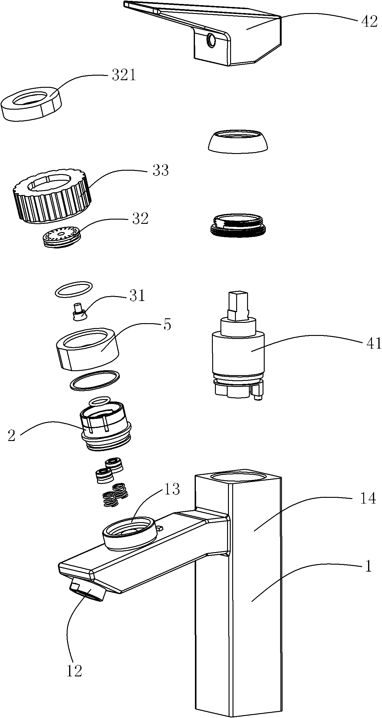
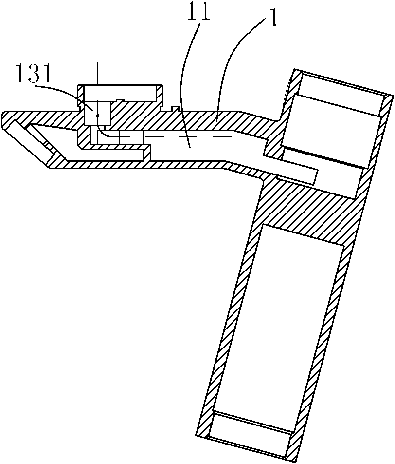
[0040] multifunctional faucet, such as figure 1 , figure 2 , image 3 , Figure 4 and Figure 5a ~ Figure 5e As shown in , it includes a faucet body 1 provided with a water inlet passage 11 , and a shower 12 with downward water outlet is arranged on the faucet body 1 .
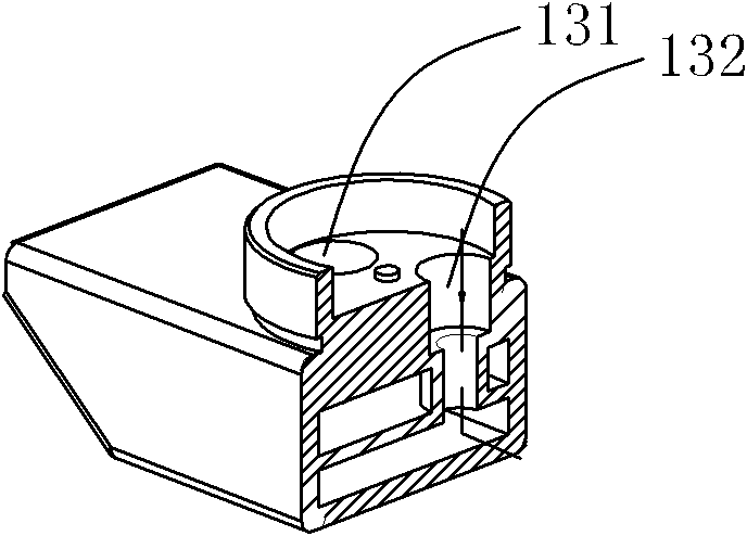
[0041] The faucet body 1 is provided with a cylindrical concave cavity 13 opening upwards, and a water inlet 131 connected to the water inlet passage 11 and a water outlet 132 connected to the shower head 12 that discharge water downwards are arranged eccentrically in the cylindrical concave cavity 13 . A spring is arranged in the water outlet 132 and the water inlet 131 with a cup.
[0042]A rotating member 2 is rotatably arranged in the cylindrical concave cavity 13, an annular flange is provided on the outer wall of the rotating member 2, and a ring is sleeved on the outside of the annular flange to press the rotating member 2 against the cylindrical concave cavity. The gland nut 20 in 13, the lower e...
Embodiment 2
[0050] like Figure 9 , Figure 10 and Figure 11 As shown in , the difference between embodiment 2 and embodiment 1 is that: the center of the bottom surface of the rotating member 2 extends downward to form a rotating shaft 26, and a shaft seat 133 matching it is arranged in the cylindrical concave cavity 13, and the rotating shaft 26 is directed to Passing through the shaft seat 133 , a nut 134 is fixed by a spacer at the bottom of the rotating shaft 133 , and the rotating member 2 is pressed into the cylindrical cavity 13 by the nut 134 .
[0051] In the rotating part 2, the inclined part of the water passage connected to the first cavity 24 extends downwards, and an opening 243 is formed on the outer wall of the rotating part 2, and the opening 243 is sealed by a sealing plug 244; The water passage 23 of the blind hole 21 and the second blind hole 22 also extends to one side, and an opening 231 is formed on the outer wall of the rotating member 2 , and the opening 231 i...
Embodiment 3
[0054] like Figure 12 , Figure 13 , Figure 14 and Figure 15a ~ Figure 15c As shown in , the difference between embodiment 3 and embodiment 2 is that: a rotating unit is rotatably arranged in the cylindrical concave cavity 13, and the rotating unit includes a cylindrical rotating main part 20, and the rotating main part 20 The bottom surface is used to simultaneously correspond to the first through hole 201 and the second through hole 202 of the water inlet 131 and the water outlet 132 of the cylindrical concave cavity, and a third through hole distributed on the same circumference as the cylindrical concave water inlet 131 203 and a fourth through hole 204, the third through hole 203 and the fourth through hole 204 respectively upwardly form a slot 205,206, the slot 205 of the third through hole and the slot 206 of the fourth through hole The first inserting tube 301 and the second inserting tube 302 of the first connecting plate 30 are plugged together in an internal s...
PUM
 Abstract
Description
Claims
Application Information
 - R&D Engineer
- R&D Manager
- IP Professional
- Industry Leading Data Capabilities
- Powerful AI technology
- Patent DNA Extraction
Browse by: Latest US Patents, China's latest patents, Technical Efficacy Thesaurus, Application Domain, Technology Topic, Popular Technical Reports.
© 2024 PatSnap. All rights reserved.Legal|Privacy policy|Modern Slavery Act Transparency Statement|Sitemap|About US| Contact US: help@patsnap.com