


Quick Research
Generate reliable direction feasibility study reports for your R&D in just a few steps.

Technical Q&A
Discover and master advanced knowledge NOW. Basics, ideas, possibilities, all at once.

Find Solutions
As an expert in R&D theories, this can generate solutions to your technical problems instantly.

Evaluate Feasibility
Analyze your overall solution with one click, know your potential R&D risks in advance.

Monitor Landscape
Get weekly tech updates, stay abreast of the latest tech innovations and key insights.
Reflector arrangement structure in tower-type power station and tower-type solar energy utilization device
A technology for arranging structures and mirrors, applied in solar thermal devices, solar thermal energy, solar thermal power generation, etc., can solve problems such as less light energy, high local temperature, and impact on the safety performance of receiving devices
- Summary
- Abstract
- Description
- Claims
- Application Information
AI Technical Summary
Problems solved by technology
Method used
Image

Examples
Embodiment 1
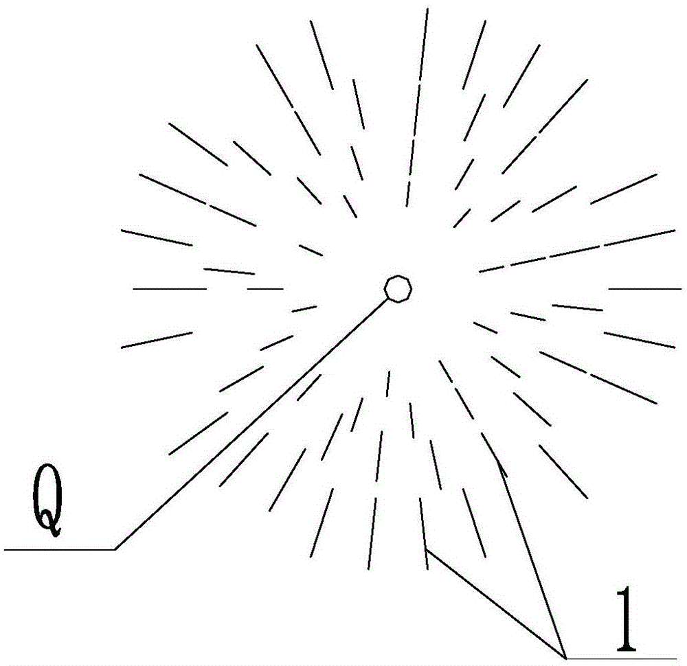
[0034] Such as figure 1 As shown, the reflector arrangement structure in the tower power station provided by this embodiment includes at least two reflector units 1 arranged around the receiving device for reflecting sunlight to the receiving device. The reflector unit 1 receives A linear light extending along the height direction of the receiving device is formed on the device;
[0035] Wherein, the mirror unit 1 includes a main axis of rotation and a plurality of mirrors arranged on the main axis of rotation, and the projection point Q formed by the receiving device on the horizontal plane along the vertical direction is located on the projection line formed by the main axis of rotation on the horizontal plane along the vertical direction on the extension line. That is, the extension directions of the main axes of rotation in the mirror unit 1 all point to the projection point Q, and a plurality of mirror units 1 are arranged around the projection point Q with the projectio...
Embodiment 2
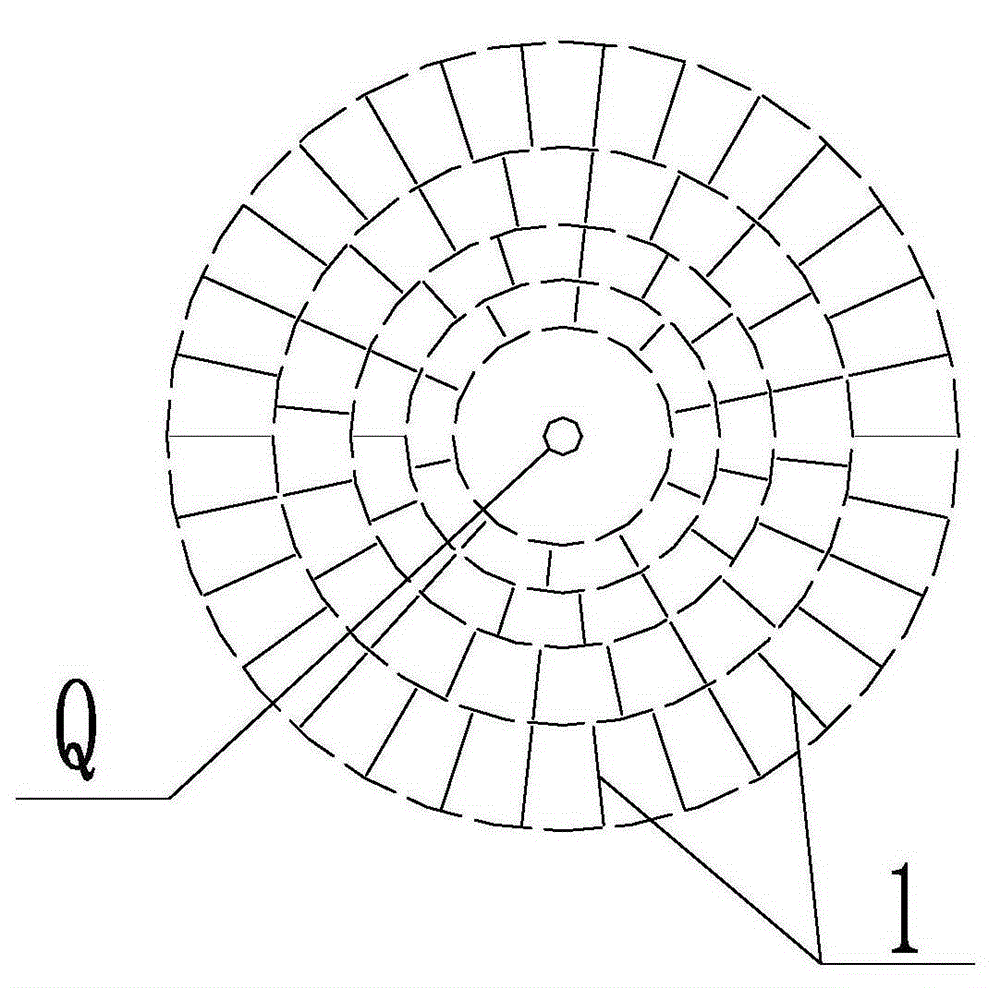
[0040] Such as Figures 2 to 4 As shown, the reflector arrangement structure in the tower power station provided by this embodiment includes at least two reflector units 1 arranged around the receiving device for reflecting sunlight to the receiving device. The reflector unit 1 receives A linear light extending along the height direction of the receiving device is formed on the device; wherein, the reflector unit includes a rotating shaft and a plurality of reflecting mirrors arranged on the rotating shaft, and the receiving device is formed on a horizontal plane along the vertical direction The projection point Q is located on the extension line of the projection line formed by the main axis of rotation in the vertical direction on the horizontal plane. And the linear light is within the receiving range of the receiving device.
[0041] Moreover, at least one annular arrangement area is formed in the direction from the inside to the outside of the projection point Q, and the...
Embodiment 3
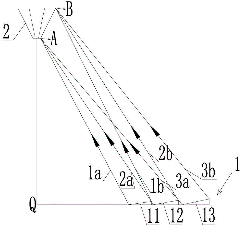
[0058] Such as Figure 5 As shown, the tower-type solar energy utilization device provided in this embodiment includes the reflector arrangement structure in the tower-type power station in embodiment 1 or embodiment 2 and a device for receiving light reflected by the reflectors in the reflector arrangement structure. Receiver 2.
[0059] The tower-type solar utilization device provided by this embodiment, by setting the main axis of rotation in the mirror unit 1 as the extension of the projection line formed by the main axis of rotation on the horizontal plane, passes through the projection point formed by the receiving device 2 on the horizontal plane in the vertical direction , so that the reflector unit 1 forms a linear light extending along the height direction of the receiving device 2 on the receiving device 2, so that the receiving device 2 receives uniform illumination.
PUM
 Abstract
Description
Claims
Application Information
 - R&D Engineer
- R&D Manager
- IP Professional
- Industry Leading Data Capabilities
- Powerful AI technology
- Patent DNA Extraction
Browse by: Latest US Patents, China's latest patents, Technical Efficacy Thesaurus, Application Domain, Technology Topic, Popular Technical Reports.
© 2024 PatSnap. All rights reserved.Legal|Privacy policy|Modern Slavery Act Transparency Statement|Sitemap|About US| Contact US: help@patsnap.com