Battery device and packaging, dismounting and recovering method of same

A technology of a battery device and a packaging method, which is applied in the disposal/recycling of fuel cells, fuel cell-type half-cells, primary cell-type half-cells, and fuel cells, etc., can solve the difficulty of packaging and recycling, and the increase of labor and mechanical costs. , the difficulty of packaging and disassembly recycling, etc., to solve the difficulty of packaging and disassembly recycling, simplify packaging and disassembly steps, and save time and cost.

Inactive Publication Date: 2011-01-12
OPEN MINDER GROUP
View PDF3 Cites 8 Cited by
  • Summary
  • Abstract
  • Description
  • Claims
  • Application Information

AI Technical Summary

Problems solved by technology

However, in order to obtain a better packaging effect and safety in the structure of the current fuel cell, a complex packaging mechanism is added, resulting in an increase in the volume of the fuel cell, which cannot be quickly disassembled or recycled. If multiple fuel cells are connected in series or in parallel When a single battery, or a hybrid mechanism composed of other fuel tanks is added, the difficulty of packaging, disassembling and recycling the device also increases
In addition, if the fuel of the fuel cell is exhausted, it needs to be sent to the fuel cell design manufacturer or the fuel cell maintenance manufacturer, and then disassembled and repackaged in complex and cumbersome steps, which further results in a huge increase in manpower and mechanical costs. Increase
[0007] Therefore, how to provide users with a battery device with a simple structure, which can be conveniently and quickly packaged and disassembled for recycling, so as to solve the problems of complex structure of battery devices and difficulties in packaging and recycling in the prior art, so as to save time and cost. It has become an urgent problem to be solved by all walks of life in the society

Method used


Image

  • Battery device and packaging, dismounting and recovering method of same
  • Battery device and packaging, dismounting and recovering method of same
  • Battery device and packaging, dismounting and recovering method of same

Examples


Embodiment Construction

[0053] Embodiments of the present invention are described below through specific examples, and those skilled in the art can easily understand other advantages and effects of the present invention from the content disclosed in this specification. The present invention can also be implemented or applied through other different specific examples, and various modifications and changes can be made to the details in this specification based on different viewpoints and applications without departing from the spirit of the present invention.

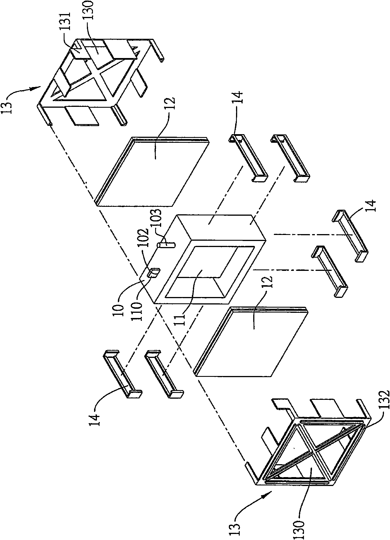
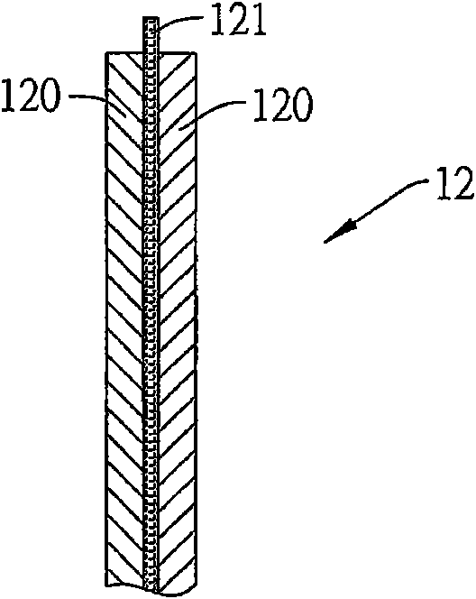
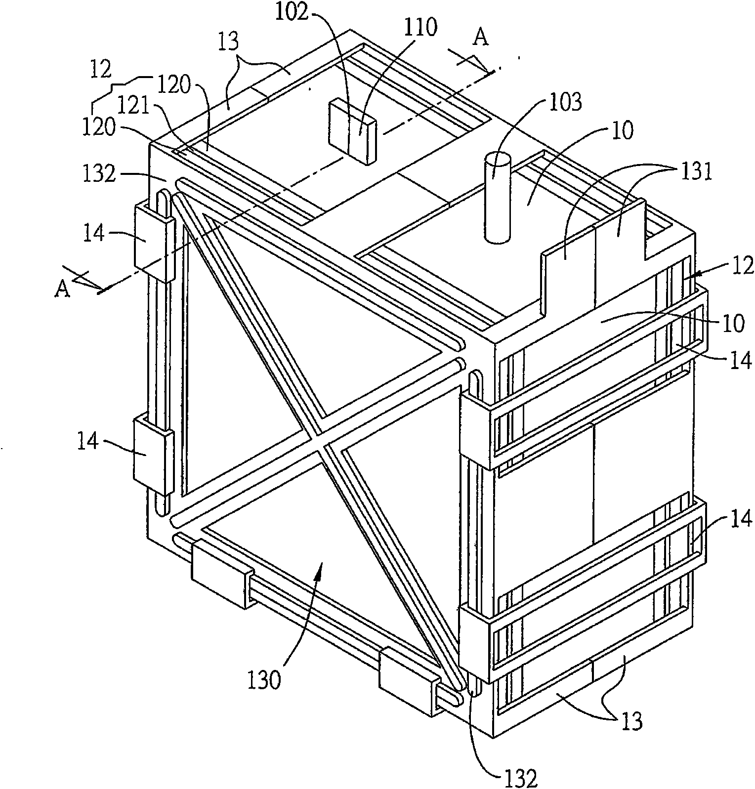
[0054] see Figure 1A , which is a three-dimensional exploded schematic view of the battery device 1 of the present invention. As shown in the figure, the battery device 1 includes: a reaction tank frame 10, an anode conductive component 11, two cathode conductive components 12, a metal fixing piece 13, and a buckle piece 14.

[0055] The reaction tank frame 10 is made of materials such as plastics, artificial rubber, natural rubber or ethylene ...


PUM

PropertyMeasurementUnit
thicknessaaaaaaaaaa

Abstract

The invention relates to a battery device and a packaging, dismounting and recovering method of same. The method comprises the following steps of: firstly, arranging an anode conducting assembly in a reaction tank frame, and protruding an anode conducting bump out of the reaction tank frame; subsequently, respectively covering a first opening and a second opening of the reaction tank frame by using two groups of cathode conducting assemblies to form a reaction area capable of accommodating electrolyte; subsequently, laying a metal fixing part on the surfaces of the cathode conducting assemblies and the reaction tank frame; and finally, fastening the metal fixing part by using a fastener. Thus, the battery device provided by the invention for a user has the characteristics of simple structure, rapid packaging, dismountability and recyclability through special structural design, and thus, the problems of difficult packaging and dismounting, difficult recovering and the like caused by complex structure of the traditional battery device are solved.

Description

technical field [0001] The present invention relates to a battery device, a method for packaging the battery device, and a method for disassembling and recycling the battery device. More specifically, it relates to a battery device that can be quickly packaged, disassembled and recycled. Background technique [0002] Today's power supply sources, in addition to emerging solar power, wind power, hydropower, tidal power and geothermal power, most of them still use thermal power or nuclear power to provide the public with a stable source of power supply. However, thermal power generation and nuclear power generation have serious environmental pollution and low conversion efficiency, while solar power generation, wind power generation, hydropower generation, tidal power generation or geothermal power generation still need breakthroughs in terms of technology and equipment for stable power supply. Therefore, fuel cells, which convert chemical energy into electricity, are graduall...

Claims


Application Information

Patent Timeline
Patent Type & Authority Applications(China)
IPC IPC(8): H01M8/00H01M12/06H01M8/008
CPCY02E60/50
Inventor 黄学正张耿荣李国霖赵允正李富生
Owner OPEN MINDER GROUP
Why Eureka
Try Eureka