


Quick Research
Generate reliable direction feasibility study reports for your R&D in just a few steps.

Technical Q&A
Discover and master advanced knowledge NOW. Basics, ideas, possibilities, all at once.

Find Solutions
As an expert in R&D theories, this can generate solutions to your technical problems instantly.

Evaluate Feasibility
Analyze your overall solution with one click, know your potential R&D risks in advance.

Monitor Landscape
Get weekly tech updates, stay abreast of the latest tech innovations and key insights.
Submersible mixer with cutting function
A submersible mixer and belt cutting technology, applied in the direction of aerobic process treatment, sustainable biological treatment, etc., can solve the problems of easy entanglement of dirt and fibrous dirt, easy entry of particulate impurities, easy damage of mechanical seals, etc., and achieve mechanical seal Good, prevents dirt from entanglement, and protects mechanical seals
- Summary
- Abstract
- Description
- Claims
- Application Information
AI Technical Summary
Problems solved by technology
Method used
Image


Examples
Embodiment 1
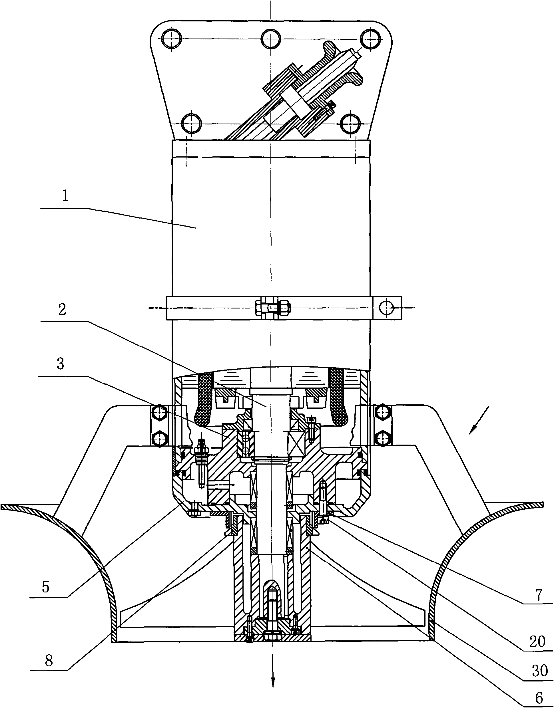
[0022] like figure 1 Shown: Preferred Embodiment 1 of the present invention: including submersible motor 1, rotating shaft 2 located at the output shaft end of submersible motor 1, bearing housing 3 located on the outer periphery of rotating shaft 2, mechanical seal seat 5 located below bearing housing 3, and the rotating shaft 1. The fixedly connected propeller 6 also includes a cutting device. The cutting device is composed of a fixed knife 7 and a rotary knife 8 with clearance fit. The fixed knife 7 is set on the mechanical seal seat 5, and the rotary knife 8 is set on the propeller 6. The area is located at the propeller 6 inlet.
[0023] The fixed knife 7 is connected with the mechanical seal seat 5 and the bearing seat 3 through screws 20, the rotary knife 8 is connected with the propeller 6 through a tight fit, and the propeller 6 is coaxial with the submersible motor 1. When working, the submersible motor 1 drives the propeller 6 Rotating, the sewage is guided by the ...
Embodiment 2
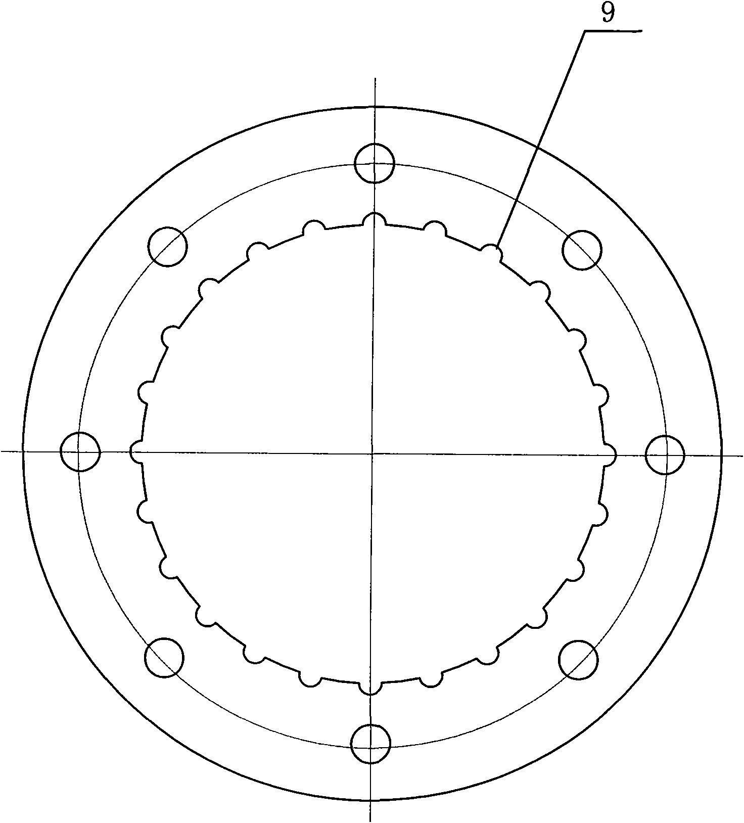
[0025] Preferred embodiment 2 of the present invention: the basic structure is the same as preferred embodiment 1, the difference is that the number of cutting grooves 9 is 18, the number of water channels 10 on the rotary knife 8 is 5, and the shafts of the guide rings 11, 12 The dip angle is 50°.
Embodiment 3
[0026] Preferred embodiment three of the present invention: the basic structure is the same as the preferred embodiment one, the difference is that the number of cutting grooves 9 is 24, the number of water channels 10 on the rotary knife 8 is 5, and the shafts of the guide rings 11, 12 The dip angle is 60°.
[0027] In the present invention, because the fixed knife 7 cooperates with the rotary knife 8 clearance, and the gap is small, before the dirt enters the propeller 6 inlet edge, it is first introduced into the cutting area by the guide rings 11, 12 of the rotary knife 8 and cuts. The number of cutting grooves 9 on the 7 is relatively large, being 12-24, and the number of water passage grooves 10 on the rotary knife 8 is 3 to 5, so the dirt by the present invention is cut up to more than 300 times per second, so The cutting effect is good, and the dirt is effectively shredded, thereby effectively preventing the dirt from winding the propeller 6 and preventing the motor fr...
PUM
 Abstract
Description
Claims
Application Information
 - R&D Engineer
- R&D Manager
- IP Professional
- Industry Leading Data Capabilities
- Powerful AI technology
- Patent DNA Extraction
Browse by: Latest US Patents, China's latest patents, Technical Efficacy Thesaurus, Application Domain, Technology Topic, Popular Technical Reports.
© 2024 PatSnap. All rights reserved.Legal|Privacy policy|Modern Slavery Act Transparency Statement|Sitemap|About US| Contact US: help@patsnap.com