
Linear motor

A linear motor and linear motion technology, applied in the direction of electric components, electromechanical devices, electrical components, etc., can solve the problems that the cost is difficult to achieve, the cooling efficiency cannot be further improved, and the effect of increasing the thrust can be achieved

Active Publication Date: 2014-03-12
THK CO LTD
View PDF11 Cites 0 Cited by
  • Summary
  • Abstract
  • Description
  • Claims
  • Application Information

AI Technical Summary

Problems solved by technology

[0011] However, replacing copper with gold or superconductors is cost-prohibitive
Moreover, the method of forming heat sinks on the shell or core of the coil to dissipate the heat needs to be devised in terms of structure, and the cooling efficiency cannot be further improved.

Method used


Image

  • Linear motor
  • Linear motor
  • Linear motor

Examples


Embodiment

[0107] In the flat linear motor, a molding material having a thermal conductivity of 6 W / (m·K) is used for the bobbin and the molded body. Then, the temperature of the coil 14 when the current value I was changed by x1, x1.15, and x1.63 times was measured.

[0108] Figure 15 A graph showing measurement results. In the figure (A) represents the current value I×1 times, (B) represents the current value I×1.15 times, (C) represents the current value I×1.63 times. exist Figure 15 In the comparative example of , a liquid crystal polymer was used for the bobbin, and an epoxy resin was used for the molded body.

[0109] As shown in the examples of the present invention, it can be seen that the temperature of the coil can be suppressed by using a material with high thermal conductivity for the bobbin and the molded body. And, as shown in (B) and (C) in the figure, the temperature (91.5 degrees) of the coil of the comparative example when the current value I×1.15 times and the te...


PUM


Abstract

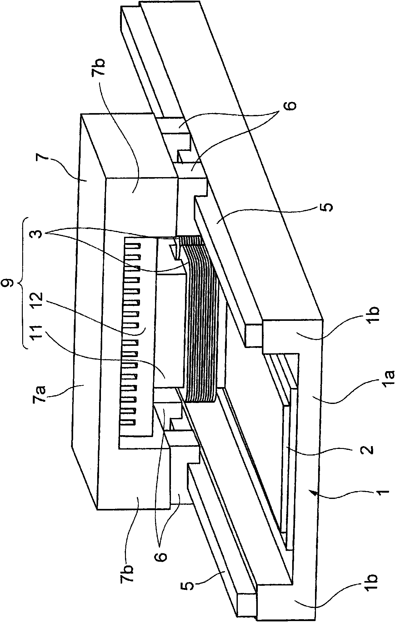
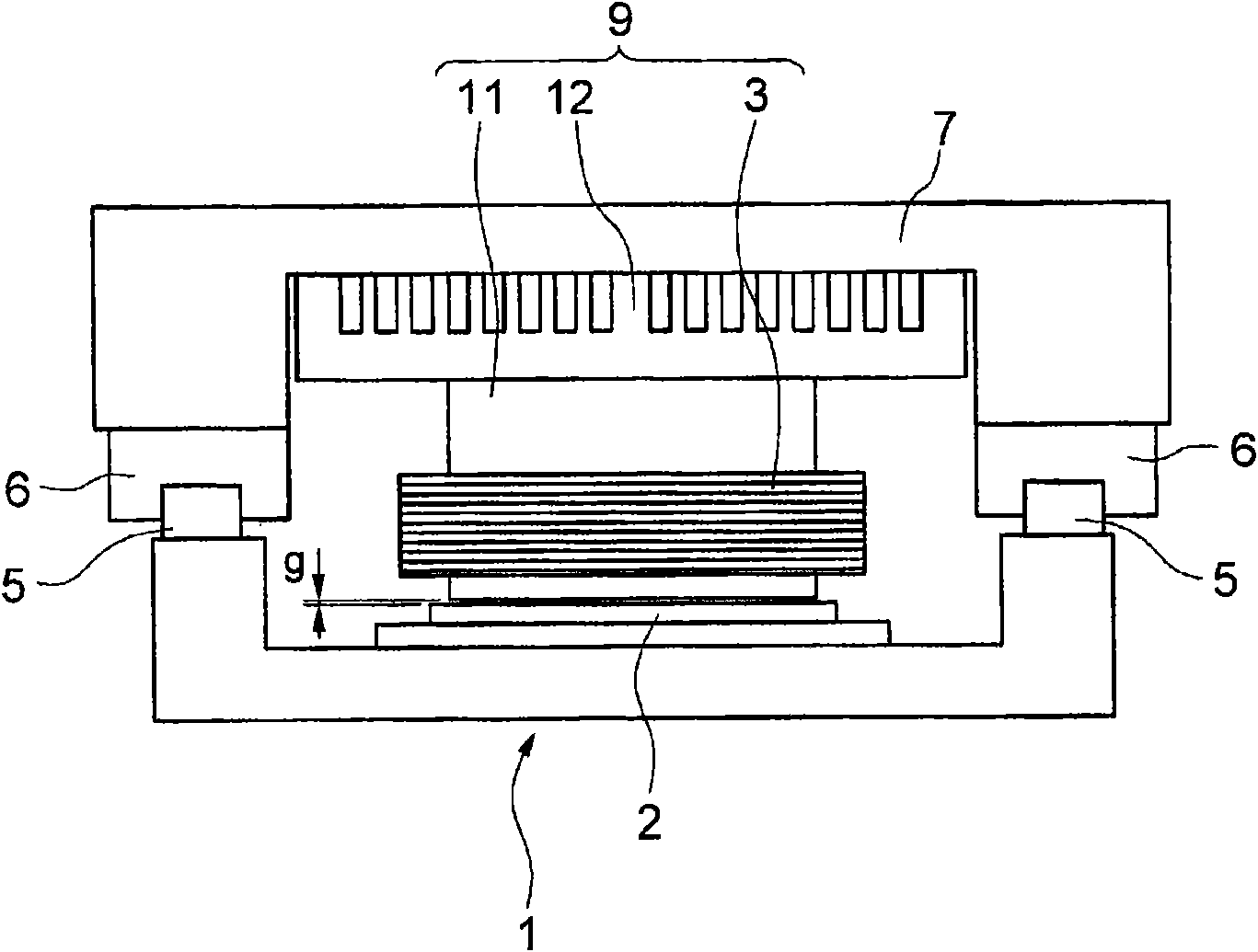
Provided is a novel linear motor, which can generate a high thrust although made compact. The linear motor comprises a field magnet (2) having N-poles and S-poles arrayed alternately in a direction for rectilinear motions, and an armature (9) for rectilinear motions relative to the field magnet (2). The armature (9) includes a plurality of coils (3) opposed through clearances to the field magnet (2), a core (11) having a plurality of comb teeth (11a to 11c) inserted individually into the coils (3), and bobbins (14) interposed between the individual coils (3) and the individual comb teeth (11a to 11c). The bobbins (14) are made of an insulator, and have a thermal conductivity of 2W / (m·K) or higher. The insulating material having the thermal conductivity of 2W / (m·K) or higher is used for the bobbins (14), and the thermal conductivity can be improved to ten times or higher than that of bobbins made of insulating paper. Thus, the heat to be generated from the coils (3) can be effectively released to the core (11).

Description

technical field [0001] The present invention relates to a linear motor in which a thrust force for linear motion is obtained by a magnetic field generated by an exciting magnet and an electric current flowing through a coil. Background technique [0002] Linear motors are divided into flat linear motors in which a long and thin plate-shaped field magnet faces across a gap, and rod-type linear motors in which a cylindrical armature surrounds a rod (shaft)-shaped field magnet (also called a shaft type). ) of the linear motor. [0003] In a flat linear motor, an armature moves linearly relative to a field magnet formed in an elongated plate shape. The field magnet is a member in which a plurality of flat magnets are arranged so that N poles and S poles are alternately formed on the surface. The armature has coils of U, V, and W phases facing the field magnet across a magnetic gap. When a three-phase alternating current flows through the coil, a thrust force for linear motion...

Claims


Application Information

Patent Timeline
Patent Type & Authority Patents(China)
IPC IPC(8): H02K41/03
CPCH02K3/522H02K3/325H02K9/22H02K41/03H02K9/223
Inventor 浅生利之山中修平
Owner THK CO LTD
Learn More