Automatic capacitance-adjusting capacitor device

A capacitor and automatic adjustment technology, applied in the direction of reactive power adjustment/elimination/compensation, reactive power compensation, etc., can solve problems such as large power factor fluctuations, increased line losses, increased power supply system losses, etc., to solve the problem of no Overcompensation and undercompensation problems, improve power factor, and ensure the effect of power supply quality

Inactive Publication Date: 2011-01-05
NINGBO TIANAN GRP CO LTD
View PDF5 Cites 2 Cited by
  • Summary
  • Abstract
  • Description
  • Claims
  • Application Information

AI Technical Summary

Problems solved by technology

[0002] Since the reactive power in the power system occupies the capacity of the power supply and distribution equipment and increases the loss of the line, the grid voltage drops and the power factor decreases, which seriously affects the power quality and the economic operation of the grid. From the perspective of power users , the reactive power cannot be balanced locally, and the intuitive performance is that the power factor is low, and the reactive power impact caused by the grid voltage drop
Voltage fluctuation and flicker; the generated high-order harmonics distort the grid voltage, causing a series of adverse effects such as protection device malfunction, capacitor overload and overvoltage, increased loss of electrical equipment, heat generation, and easy aging of insulation
With the development of the national economy, the power loads of various industries have increased significantly. Among the newly added loads, the reactive power load has increased the loss of the power supply system. However, most of the substations in my country's current distribution network use fixed collective capacitor banks for reactive power compensation. Due to the lack of reactive power adjustment means, the power factor fluctuates greatly during the peak and valley of power supply, and the problem of over-compensation and under-compensation often occurs

Method used


Image

  • Automatic capacitance-adjusting capacitor device
  • Automatic capacitance-adjusting capacitor device
  • Automatic capacitance-adjusting capacitor device

Examples


Embodiment Construction

[0019] The present invention will be described in detail below in conjunction with the embodiments and accompanying drawings, but the present invention is not limited thereto.

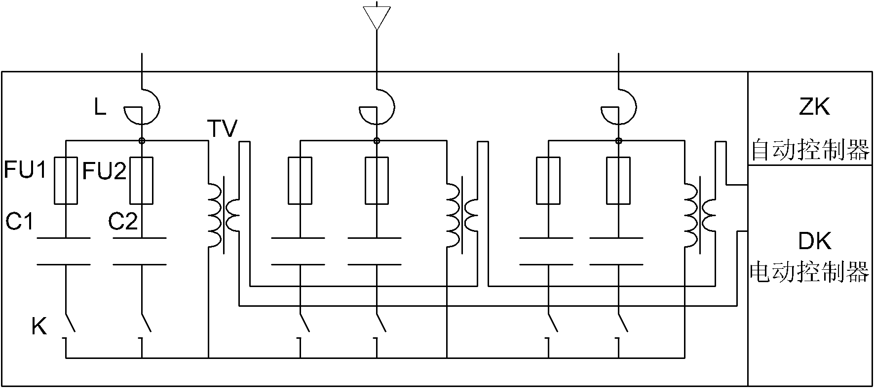
[0020] Such as figure 1 As shown, an automatic capacity-adjusting capacitor device includes: reactor L, capacitor C1 (including fuse FU1), capacitor C2 (including fuse FU2), non-excitation adjustment switch K, discharge coil TV, electric control controller DK and automatic controller ZK.

[0021] Among them, the capacitor C1 and one contact of the non-excitation regulating switch K are connected in series to form a capacitor branch, the capacitor C2 and the other contact of the non-excitation regulating switch K are connected in series to form another capacitor branch, and the two branches are connected in parallel to form a parallel capacitor bank. The parallel capacitor group is connected in series with the reactor L, and the parallel capacitor group is connected in parallel with the discharge coil ...


PUM


Abstract

The invention discloses an automatic capacitance-adjusting capacitor device. The device comprises an integrated parallel capacitor, a non-excited regulating switch, an electric controller and an automatic controller, wherein the integrated parallel capacitor comprises capacitor units of which three phases are the same, and each phase of capacitor unit consists of a parallel capacitor bank, a reactor and a discharge coil; the wire inlet end of the parallel capacitor bank is connected in series with the reactor, and the parallel capacitor bank is connected in parallel with the discharge coil; two parallel capacitors are arranged in the parallel capacitor bank, and the wire outlet end of each capacitor is connected in series with different contacts of the non-excited regulating switch to form a neutral point; and a secondary circuit of the non-excited regulating switch is connected with the electric controller, and the electric controller is connected with the automatic controller. The automatic capacitance-adjusting capacitor device overcomes the defect that the capacitance cannot be adjusted automatically in the conventional integrated capacitor, compensates the reactive power of electric power circuits automatically according to the comprehensive judgment on power grid voltage and power factors, and solves the problems of the overcompensation and undercompensation of the reactive power.

Description

technical field [0001] The invention belongs to the technical field of power devices, and in particular relates to reactive power compensation capacitors widely used in power systems. Background technique [0002] Since the reactive power in the power system occupies the capacity of the power supply and distribution equipment and increases the loss of the line, the grid voltage drops and the power factor decreases, which seriously affects the power quality and the economic operation of the grid. From the perspective of power users , The reactive power cannot be balanced on the spot, and the intuitive performance is that the power factor is low, and the generated reactive power impact causes the voltage drop of the grid. Voltage fluctuation and flicker; the generated high-order harmonics distort the grid voltage, causing a series of adverse effects such as protection device malfunction, capacitor overload and overvoltage, increased loss of electrical equipment, heat generatio...

Claims


Application Information

Patent Timeline
Patent Type & Authority Applications(China)
IPC IPC(8): H02J3/18
CPCY02E40/30
Inventor 程晓弘张黎明董海林伟卫尚荣
Owner NINGBO TIANAN GRP CO LTD
Why Eureka
Try Eureka