
Device for online monitoring lightning current and lightning voltage waveform parameters of overhead transmission line

A technology for overhead transmission lines and voltage waveforms, which can be used in the measurement of current/voltage, measurement devices, and electrical variables, etc., and can solve problems such as unfavorable popularization, complex equipment, and errors in calculation data.

Inactive Publication Date: 2011-01-05
XI AN JIAOTONG UNIV
View PDF4 Cites 52 Cited by
  • Summary
  • Abstract
  • Description
  • Claims
  • Application Information

AI Technical Summary

Problems solved by technology

Some problems were also found in the use, such as complex equipment, large initial investment, which is not conducive to popularization, the positioning system itself has certain errors and detection dead zones, terrain factors interfere greatly with the detection station, and calculation data has errors, etc.
[0005] 3) Tape method: Dr. Crouch in the United States uses a highly sensitive recording tape to determine the magnitude of the measured lightning current amplitude. Professor Zhang Yuanfang in China has developed a tape-type lightning current recorder based on this method, but this method can only measure The magnitude of the lightning current is far from enough for a comprehensive study of the mechanism of lightning strikes on transmission lines and its influencing factors

Method used


Image

  • Device for online monitoring lightning current and lightning voltage waveform parameters of overhead transmission line
  • Device for online monitoring lightning current and lightning voltage waveform parameters of overhead transmission line
  • Device for online monitoring lightning current and lightning voltage waveform parameters of overhead transmission line

Examples


Embodiment Construction

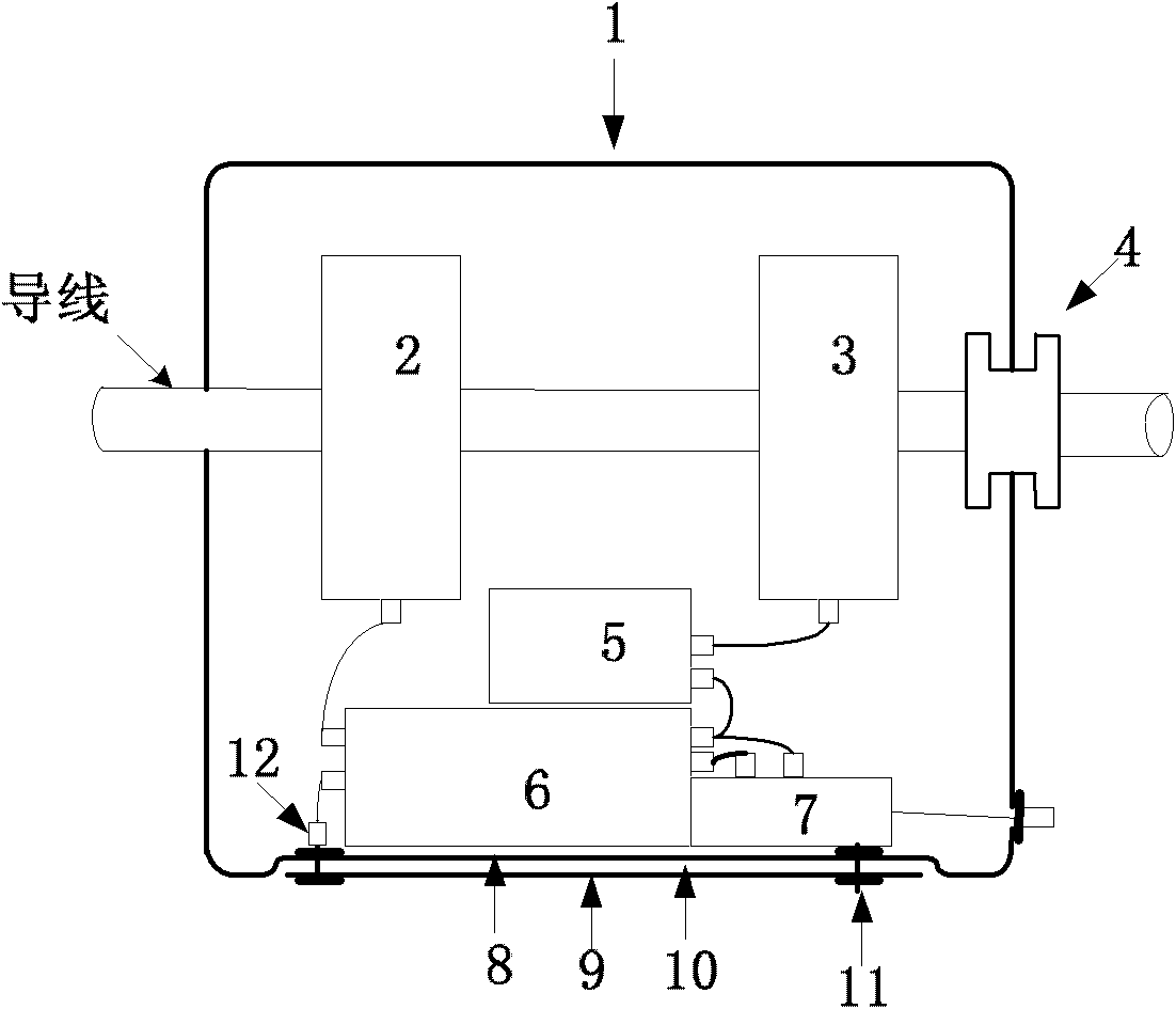
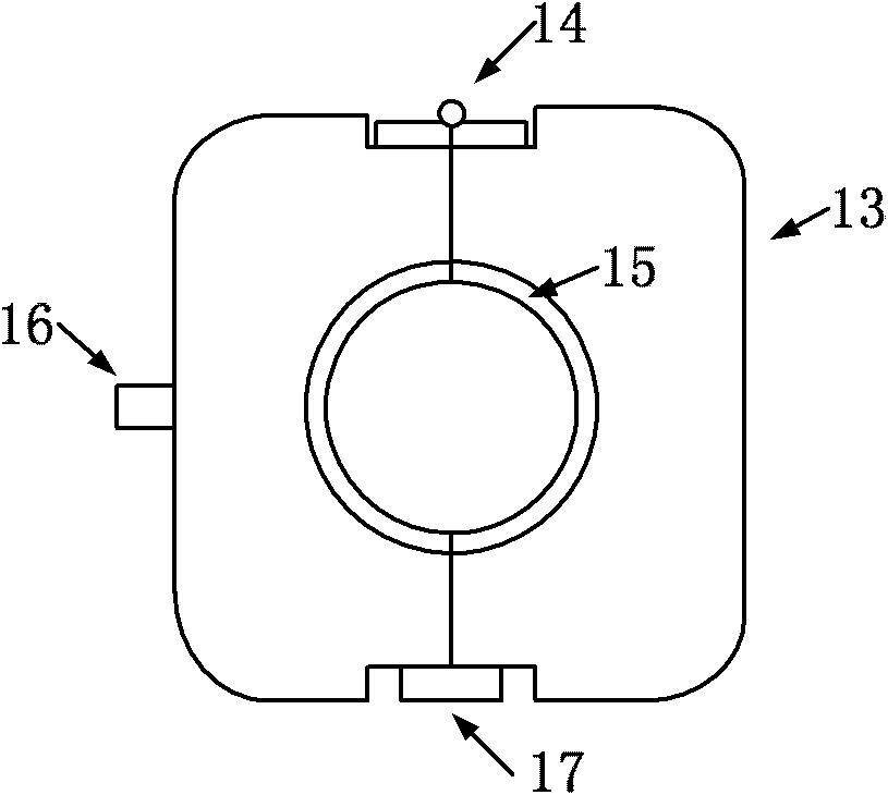
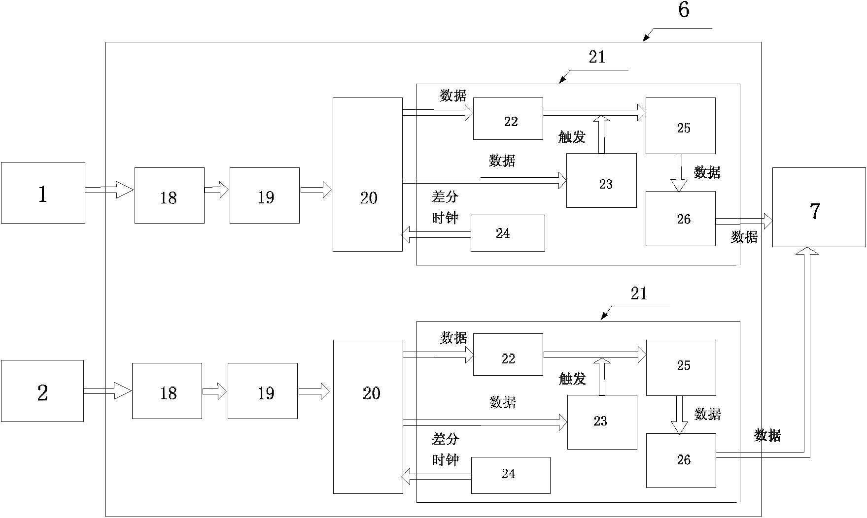
[0017] Reference figure 1 As shown, the upper and lower half shell clamps of the voltage sensor 1 are hung on the conductor of the overhead transmission line or the sub-conductor of the split conductor. One end is tightly fixed and electrically contacted with the conductor to form an equipotential. The other end is fixed and insulated with the conductor by the insulator 4 isolation. The voltage sensor 1 is a capacitive coupling voltage sensor, which conforms to the principle of a capacitive voltage divider. The voltage sensor 1 is made of aluminum and includes an upper electrode 8, a polyimide film 9, and a lower electrode 10. The lower electrode 10 is fixed on the lower side of the upper electrode 8 by an insulating screw 11, and the polyimide film 9 is sandwiched between the two electrodes to form High-voltage arm capacitance; the stray capacitance between the bottom electrode 10 and the ground and surrounding ground bodies constitutes the low-voltage arm capacitance. The fl...


PUM


Abstract

The invention discloses a device for online monitoring lightning current and lightning voltage waveform parameters of an overhead transmission line, relating to the fields of lightning information measurement and lightening prevention design. The monitoring system is directly installed on a sub-wire of a single-phase wire or a split wire of the overhead transmission line, a voltage sensor and a current sensor respectively monitor a lightning current signal and a lightning voltage signal, and the two paths of signals are sent to a GPRS (General Packet Radio Service) network by a GPRS module through a signal acquisition and processing module. When the system runs normally, the induced voltage of a check coil is processed and then directly supplies power to the signal acquisition and processing module and the GPRS module and fully charges a lithium ion storage battery; and when the wire has the lightning current and the system is power failure, the lithium ion storage battery supplies power for converting an instant power failure protective capacitor to prevent data loss. The invention provides original data for lightning positioning of the transmission line and the lightning current and lightning voltage waveform parameters of a back calculation lightning stroke point and has the advantages of simple manufacturing process, small size and convenient installation.

Description

Technical field [0001] The invention relates to the field of lightning information measurement, in particular to online monitoring of the lightning current and lightning voltage waveform parameters of overhead transmission lines. Background technique [0002] In our country, lightning damage is still the most important factor affecting the safe operation of power systems. High-voltage line trips caused by lightning strikes account for about 70% of the total number of line trips. Therefore, the monitoring of lightning parameters and the understanding of the physical process of lightning have very important practical application value for lightning protection design such as power and communication. The current methods for monitoring lightning current parameters mainly include the following: [0003] 1) Magnetic steel rod method: It is a traditional method of measuring lightning current, but the magnetic steel rod method has a great defect, that is, when there are two lightning strik...

Claims


Application Information

Patent Timeline
IPC IPC(8): G01R19/00
Inventor 汲胜昌王春杰张乔根
Owner XI AN JIAOTONG UNIV
Learn More