
Detection equipment of air tightness of shell

An air-tightness detection and shell technology, which is used in liquid/vacuum measurement for liquid-tightness, mechanical equipment, supporting machines, etc., can solve the problem of increasing the production cost, unstable detection quality, The operation labor intensity is high and other problems, to achieve the effect of saving manpower, simple structure and reducing labor intensity

Active Publication Date: 2011-01-05
江苏南方机电股份有限公司
View PDF5 Cites 23 Cited by
  • Summary
  • Abstract
  • Description
  • Claims
  • Application Information

AI Technical Summary

Problems solved by technology

[0003] The current air tightness test is usually carried out manually, that is, immersing the closed engine casing in water, filling the engine casing with pressurized air in the water, and observing whether the engine casing is leaking. This operation is labor-intensive and the work efficiency is high. Low, unstable detection quality
There are also some automated air tightness testing equipment, but their versatility is poor. One testing equipment is limited to the detection of one or several shells, which increases the production cost of multi-variety shell manufacturers.
In addition, the existing detection equipment uses rigid seals when multi-point sealing, and cannot effectively seal multiple points at the same time.

Method used


Image

  • Detection equipment of air tightness of shell
  • Detection equipment of air tightness of shell
  • Detection equipment of air tightness of shell

Examples


Embodiment Construction

[0029] The present invention will be further described below in conjunction with specific drawings and embodiments.

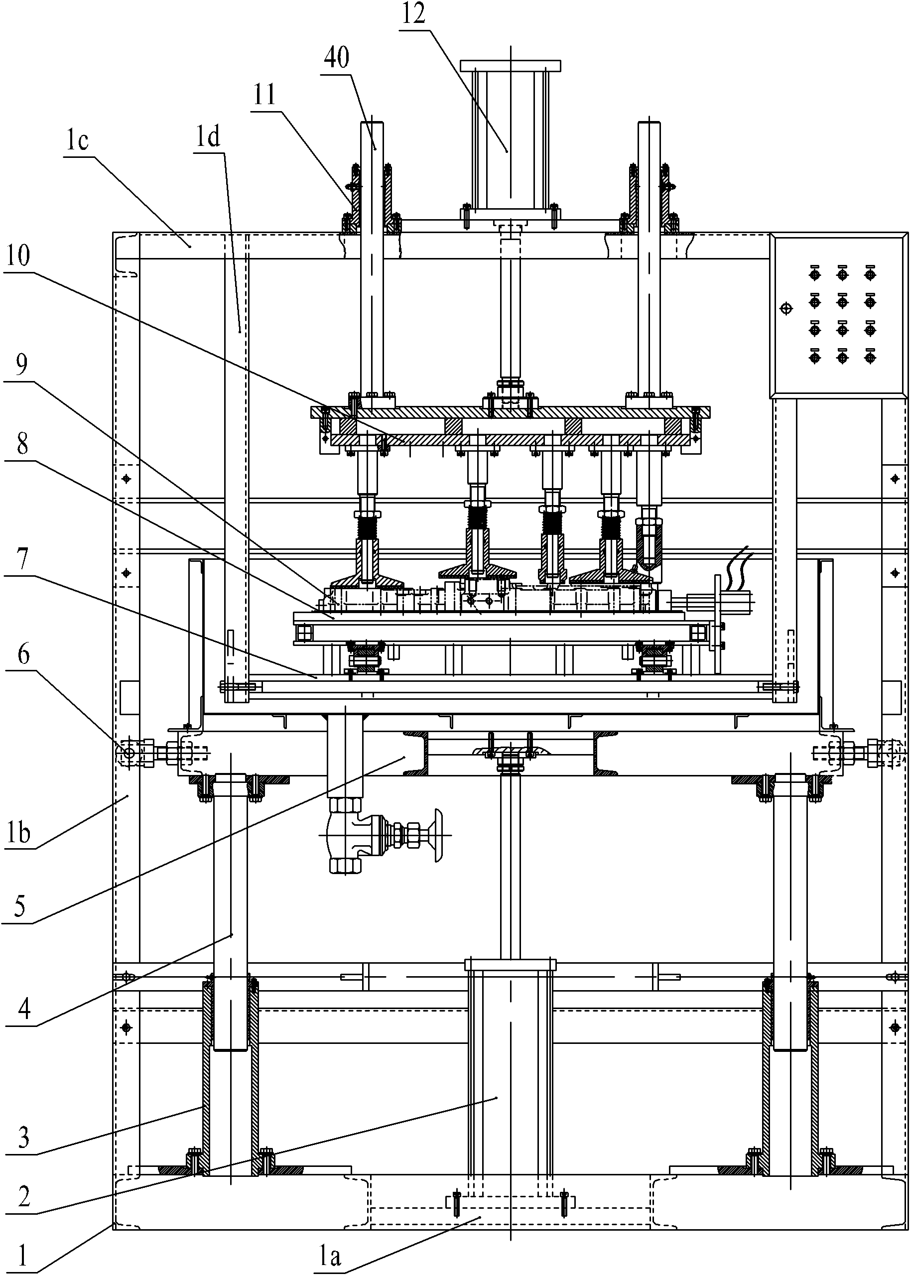
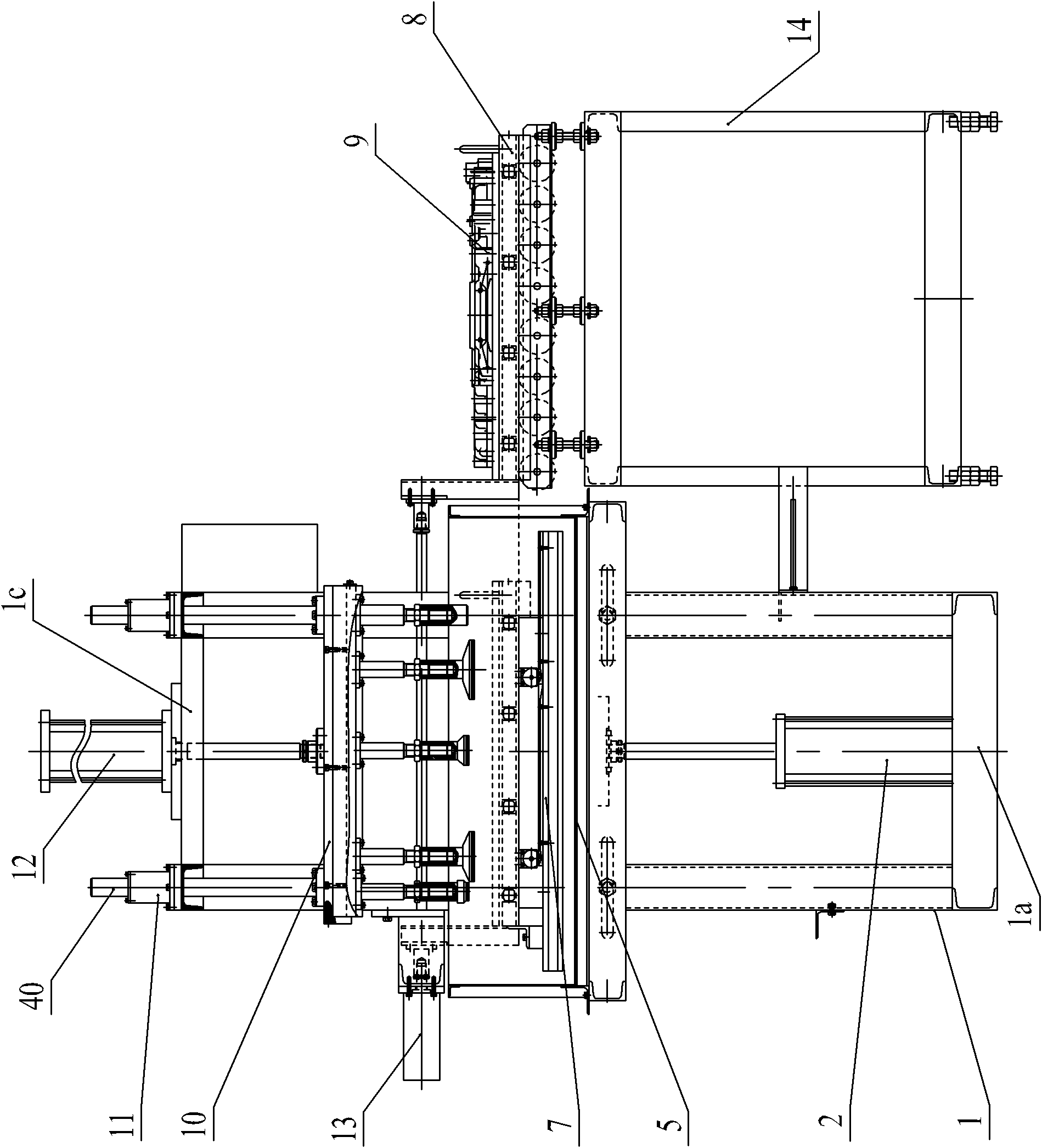
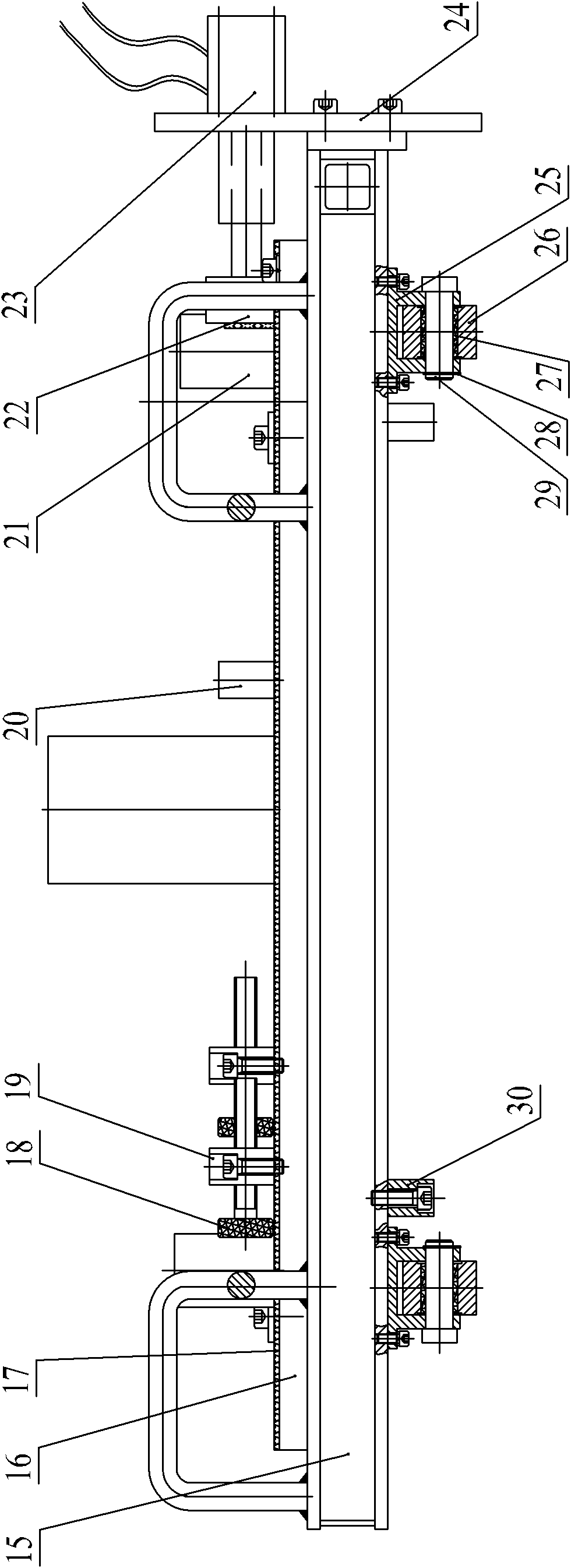
[0030] As shown in the figure: the shell air tightness testing equipment in the embodiment mainly consists of a steel frame 1, a lower oil cylinder 2, a water tank 5, a pressure-bearing suspension platform 7, a sliding table mechanism 8, an elastic frame mechanism 10, an upper oil cylinder 12 and a push-pull Oil cylinder 13 forms.

[0031] The steel frame 1 is composed of a bottom frame 1a, a column 1b, a top frame 1c and a hanger 1d. The bottom frame 1a and the top frame 1c are connected by a column 1b, and the hanger 1d is arranged under the top frame 1c and connected to the top frame 1c by screws. .

[0032] The lower oil cylinder 2 is vertically arranged, and the cylinder body of the lower oil cylinder 2 is fixed on the underframe 1a of the steel frame 1 by screws, and the piston rod of the lower oil cylinder 2 is upwardly connected to the water tank 5; F...


PUM


Abstract

The invention relates to detection equipment of air tightness of a shell. The invention adopts a technical scheme that: the cylinder body of a lower oil cylinder is fixed on a bottom frame of a steel framework; a piston rod of the lower oil cylinder is upwards connected to a water tank; a lower guide component is arranged between the water tank and the bottom frame of the steel framework; lifting rollers are arranged on two sides of the water tank respectively and are embedded in channel steels of upright posts of the steel framework; a pressure-bearing hanging table is suspended on the steel framework; a moving table mechanism is born on the pressure-bearing hanging table through a roller support arranged on a bottom lifting part; an elastic pressing frame mechanism is arranged over the moving table mechanism; the cylinder body of an upper oil cylinder is fixed on a top frame of the steel framework; a piston rod of the upper oil cylinder is downwards connected to the elastic pressing frame mechanism; an upper guide component is arranged between the elastic pressing frame mechanism and the top frame of the steel framework; a push oil cylinder is horizontally arranged; the cylinder body of the push oil cylinder is fixed on the steel framework; and the piston rod of the push oil cylinder is connected with the moving table mechanism. The detection equipment of the invention has the advantages of craft and reasonable structure, strong reliability, cost saving, good university and good sealing effect.

Description

technical field [0001] The invention belongs to the technical field of detection equipment, and in particular relates to a device for detecting the airtightness of a casing. Background technique [0002] With the rapid development of the economy, industries such as general machinery, automobiles, and excavation are also increasingly prosperous. All these industries require various power equipment such as diesel engines and gasoline engines, which lead to a substantial increase in the demand for diesel engines and gasoline engines. As a necessary part, the housing of diesel engine and gasoline engine has entered the era of mass production. The casing of the engine is usually formed by casting, and defects such as air shrinkage cavities and cracks sometimes occur during the casting process. These defects easily lead to problems such as oil leakage and oil leakage, seriously pollute the working environment of the complete machine, and cause huge waste. At the same time, there...

Claims


Application Information

Patent Timeline
Patent Type & Authority Applications(China)
IPC IPC(8): G01M3/02F16M11/04F16M11/22
Inventor 杨诗斌骆国泽王树荣胡斌顾晓明胡道军史楠楠
Owner 江苏南方机电股份有限公司
Learn More