Lighting system

A technology for lighting systems and lighting appliances, applied in the field of lighting systems, can solve problems such as difficulty in setting, achieve the effects of reducing the number of parts, improving the appearance, and reducing the number of assembly processes

Inactive Publication Date: 2011-01-05
HONDA MOTOR CO LTD
View PDF6 Cites 2 Cited by
  • Summary
  • Abstract
  • Description
  • Claims
  • Application Information

AI Technical Summary

Problems solved by technology

[0004] However, from Patent Document 1's Figure 5 It can be seen that since the first housing 62 and the reflection plate of the second lighting fixture are constituted as double layers, the lighting system becomes very heavy.
In addition, since the first housing 62 is arranged in front of the second lighting fixture reflector, there is a problem that it is difficult to set the reflection surface of the second lighting fixture reflector for uniformly reflecting light from the second light emitting surface.

Method used


Image

  • Lighting system
  • Lighting system
  • Lighting system

Examples


no. 1 example

[0063] First, a first embodiment of the present invention will be described with reference to the drawings.

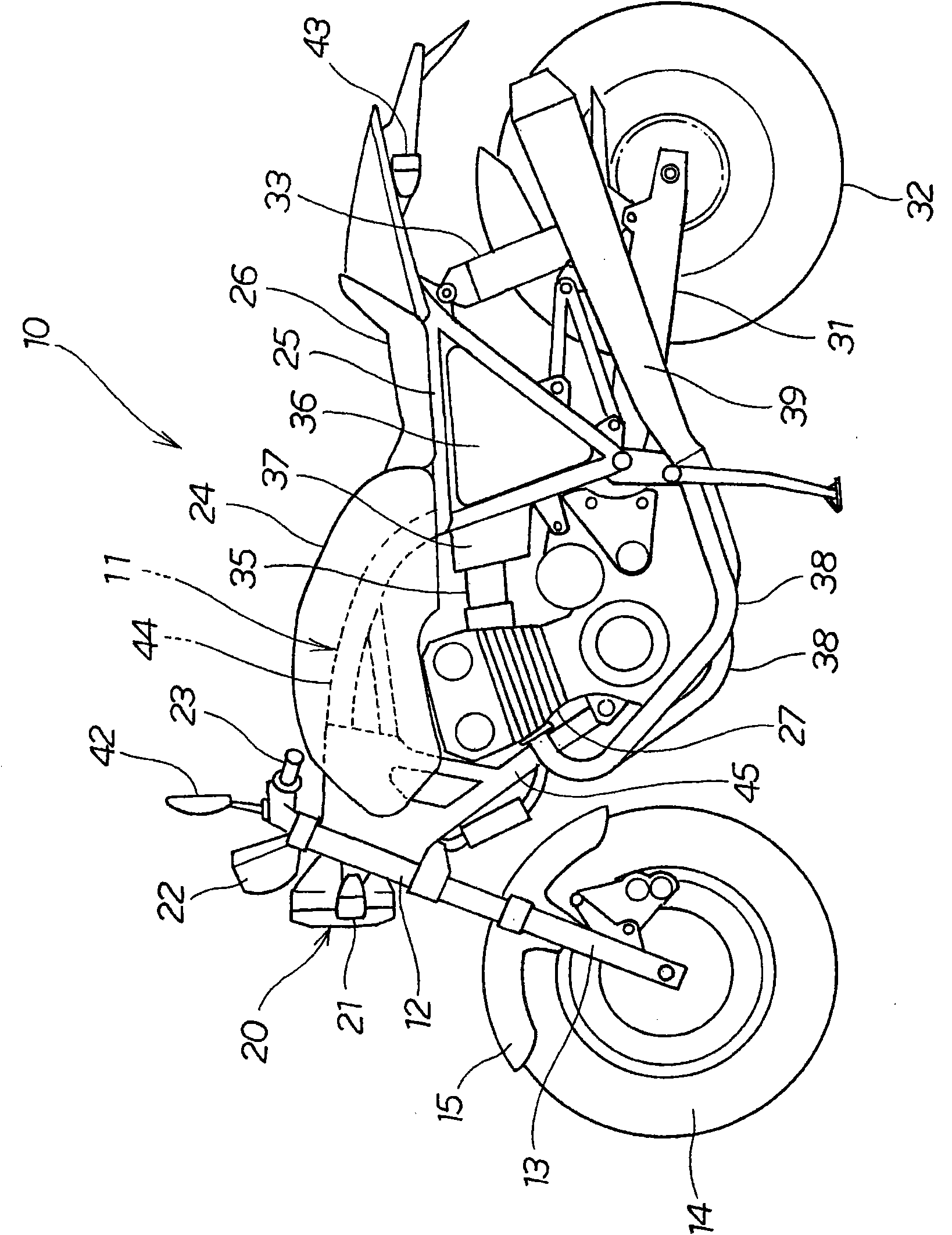
[0064] Such as figure 1As shown, a saddle-riding vehicle 10 such as a motorcycle is composed of a frame 11, a front fork 13 rotatably mounted on a head pipe 12 provided at the front end of the frame 11, and a rotatably mounted The front wheel 14 at the lower end of the front fork 13, the front wheel fender 15 installed on the front fork 13 to block the earth and stones bounced up by the front wheel 14, the headlight as the lighting system installed on the front part of the head pipe 12 20. Two front direction indicator lamps 21, instruments 22 and steering handlebars 23 as lighting systems arranged along the direction of the front and back of the drawing with the headlight 20 in the middle, and the fuel arranged on the frame 11 Box 24, the seat 26 that is installed in the seat guide rail 25 that extends rearward from vehicle frame 11, the engine 27 that is suspended ...

no. 2 example

[0107] Such as Figure 8 As shown, no spokes are provided in the headlamp 90 ( figure 2 The reference numeral 58 in the figure), so that the spacer cover 91 and the peripheral cover 92 are respectively fixed on the substrate case 93 .

[0108] In assembling such a headlamp 90 , first, the first lighting fixture 51 is attached to the annular support 95 .

[0109] On the other hand, the peripheral cover 92 is attached to the substrate case 93 .

[0110] Then, the second lighting fixture 96 with the outer peripheral cover 92 is attached to the annular support 95 on which the first lighting fixture 51 is attached.

[0111] Finally, align the boss 97 of the spacer cover 91, the inner peripheral mounting hole 98 provided on the inner peripheral portion of the substrate housing 93, and the spacer cover mounting hole 99 provided on the annular support 95, and screw them together. 102 is fixed integrally.

[0112] The second lighting fixture 96 is supported by an annular support 9...


PUM


Abstract

The invention provides a lighting system, aims to reduce the weight of the lighting system. A headlight (20) includes a first lighting apparatus (51) including a light source (61) covered with a housing (62) and an annular second lighting apparatus (52) disposed around the housing (62). In the headlight (20), the second lighting apparatus (52) is supported by an annularly formed annular stay (65) that is supported by the housing (62) and includes a plurality of light-emitting elements (54) disposed annularly so as to be radially spaced apart from an outer periphery of the first lighting apparatus (51) in a front view. The second lighting apparatus (52) is supported by the housing (62). This eliminates the need for using a housing for the exclusive use for supporting the second lighting apparatus (52). This promotes reduction in weight of the headlight (20).

Description

technical field [0001] The present invention relates to improved techniques for use in lighting systems such as headlights for saddle-riding vehicles. Background technique [0002] In order to illuminate the front of the saddle-riding vehicle, headlights are provided on the saddle-riding vehicle. For this reason, a lighting system with a special appearance is proposed, that is, around the first lighting device with a circular light-emitting surface, a second lighting device is arranged. Two lighting fixtures to form a concentric ring-shaped light-emitting surface with the first lighting fixture (for example, refer to Patent Document 1( Figure 5 )). [0003] As in Patent Document 1 Figure 5 As shown, the first light source 63 is supported by the first housing 62 , the reflector of the second lighting fixture is arranged to surround the first housing 62 , and the second light source 65 is supported by the reflector of the second lighting fixture. [0004] However, from Pate...

Claims


Application Information

Patent Timeline
Patent Type & Authority Applications(China)
IPC IPC(8): B62J6/02
CPCB62J6/02B60Q1/0052B62J6/026
Inventor 三宅川彻
Owner HONDA MOTOR CO LTD
Why Eureka
Try Eureka