Wet air control master valve

An air-controlled, wet-type technology, applied in the direction of control valve and air release valve, lift valve, valve details, etc., can solve the problems of easy adhesion of impurities, no filter screen in the intake chamber, and deviation of the piston coaxiality, to avoid valve Core sticking and seal damage, preventing impurities from entering the valve body, and ensuring a high degree of coaxiality

Active Publication Date: 2011-09-28
厦门金利业科技有限公司
View PDF2 Cites 0 Cited by
  • Summary
  • Abstract
  • Description
  • Claims
  • Application Information

AI Technical Summary

Problems solved by technology

[0005] 1) The sealing of the valve core sealing ring is realized by axial extrusion deformation between the valve core and the valve body. The valve core sealing ring is in a state of extreme deformation, which is prone to fatigue and damage, resulting in air leakage
[0006] 2) The sealing surface of the sealing ring of the valve core is facing upwards, which is easy to adhere to impurities, which are difficult to discharge and easily cause air leakage
[0007] 3) There is no filter screen in the air intake chamber, and impurities from upstream components can easily enter the valve body during air intake, which can easily cause the piston to stick or the seal to leak air
[0008] 4) There is no filter screen in the air outlet chamber. When exhausting, the impurities in the upstream parts are easy to enter the inside of the valve body, which may easily cause the piston to stick or the seal to leak.
[0009] 5) The positioning of the spool is unreliable, the spool is only positioned by the base, and there is a deviation in the coaxiality with the piston, resulting in unstable work
[0010] 6) There is no special oil tank for the piston and the base. After a long working time, dry friction will occur between the piston and the valve core, which will easily cause sticking and damage to the sealing ring.
[0011] 7) There is no filter screen at the exhaust port, and foreign impurities can easily enter the valve body, which can easily cause the piston to stick or the seal to leak air
[0012] 8) The setting of the breathing port is unreasonable, and impurities are easy to enter the valve body, which may easily cause the piston to stick or the seal to leak air
[0013] 9) There is no positioning plate for the installation of the valve body, and it cannot form an independent individual. It can only be positioned by the mounting plate, which is very inconvenient for assembly and maintenance

Method used


Image

  • Wet air control master valve
  • Wet air control master valve
  • Wet air control master valve

Examples


Embodiment Construction

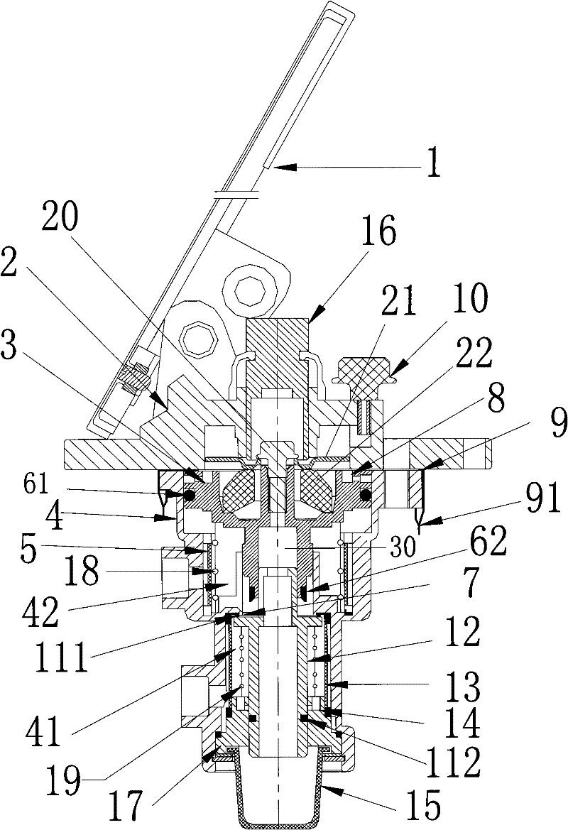
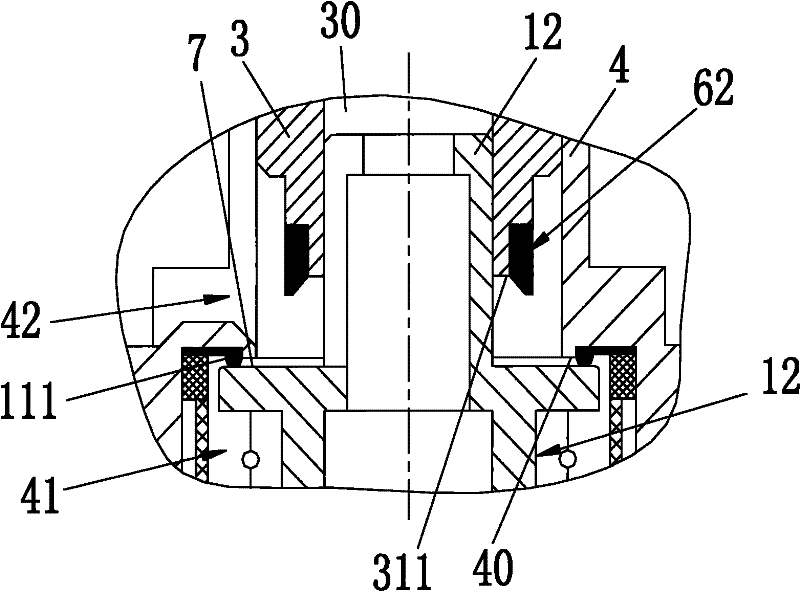
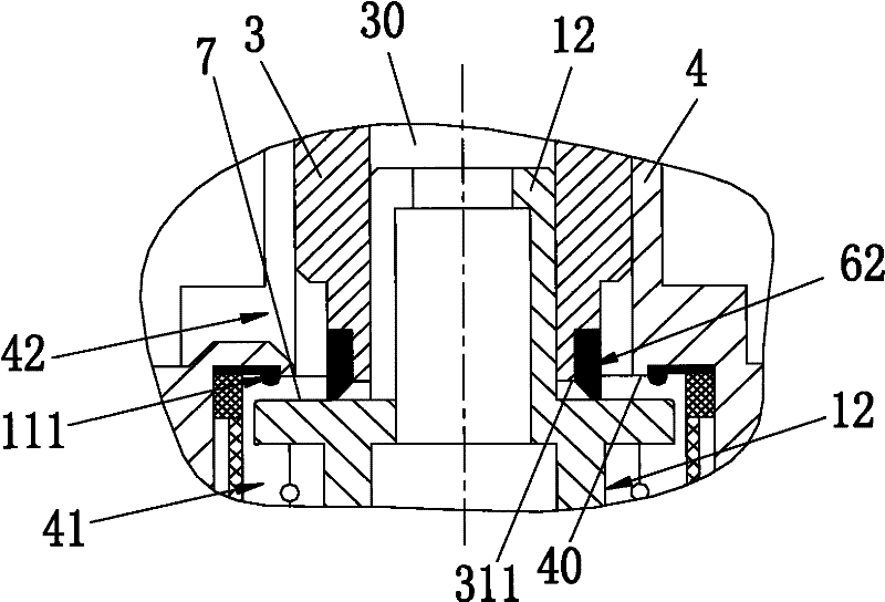
[0040] see Figure 1~3 , the embodiment of the present invention is provided with a pedal 1, a mounting plate 2, a push rod 16, a piston 3, a valve body 4, a valve core 12, a base 17, a piston return spring 18, a piston seal, a valve core return spring 19, a valve Core seal, air intake cavity filter screen 13 and air outlet cavity filter screen 5 etc.

[0041] Mounting plate 2 is fixed on the car body ( figure 1Not shown in the middle), the pedal 1 is located on the top of the mounting plate 2, and the lower end of the pedal 1 is connected with the mounting plate 2 in rotation. The push rod 16 is disposed in the mounting plate 2 and is slidingly matched with the mounting plate 2 . The pedal 1 is stepped on, and the push rod 16 is pressed to move downward. A pressing plate 21 and an elastic body 22 are arranged below the push rod 16 , and the pressing plate 21 and the elastic body 22 are connected by a fastener 20 . The push rod 16 moves downward to press the pressing plat...


PUM


Abstract

The invention discloses a wet air control master valve and relates to a pneumatic control master valve. The invention provides the wet air control master valve which can avoid the clamping stagnation of a piston and the air leakage of sealing elements, effectively improve the work reliability and be mainly used for brake systems of engineering vehicles, such as a loading machine and the like. Thewet air control master valve comprises a mounting plate, a push rod, a valve body, the piston, a valve core, a base, a piston return spring, a piston sealing element, a valve core return spring, a valve core sealing element, an air inlet cavity filter mesh and an air outlet cavity filter mesh, wherein the push rod is arranged in the mounting plate, the valve body is fixed below the mounting plate, an air inlet cavity and an air outlet cavity are arranged in an inner cavity of the valve body, the piston and the piston return spring are arranged in the air outlet cavity of the valve body, the piston is connected with the push rod, the piston is matched with the valve body, and the valve core and the valve core return spring are arranged in the air inlet cavity of the valve body; the upper end of the valve core is positioned at a central hole of the piston, and the lower end is positioned at the central hole of the base; and an upper valve core sealing ring and a lower valve core sealingring are arranged on the valve core sealing element, the upper valve core sealing ring is mounted in an upper valve core sealing ring groove on the wall of the air inlet cavity of the valve body, andthe air inlet cavity and the air outlet cavity of the valve body are separated by the upper valve core sealing ring.

Description

technical field [0001] The invention relates to a pneumatic control master valve, in particular to a wet air control master valve applicable to the braking system of engineering vehicles such as loaders. Background technique [0002] The working environment of engineering vehicles such as loaders is often very harsh, and frequent forward and backward braking is required during work, resulting in huge losses to the braking system, so the reliability of the braking system is highly required. The main control valve of the existing loader braking system is generally a non-wet air control main valve. The conventional structure of the non-wet air control main valve is as follows: Figure 4 Shown: [0003] Figure 4 Among them, each label indicates: 30. Pedal, 31. Ejector, 32. Mounting plate, 33. Piston, 34. Valve body, 35. Air outlet cavity, 36. Valve core sealing ring, 37. Air intake cavity, 38. Valve Core, 39. Base. Its working principle is: when braking, step on the pedal 31 ...

Claims


Application Information

Patent Timeline
Patent Type & Authority Patents(China)
IPC IPC(8): F16K1/00F16K1/34F16K31/62F16K27/02B01D35/04B60T15/02
Inventor 李玉喜
Owner 厦门金利业科技有限公司
Why Eureka
Try Eureka