
Unwinding device for warp knitting machine

An unwinding device and warp knitting machine technology, which is applied in warp knitting, textiles, papermaking, knitting, etc., can solve problems such as poor unwinding effect, and achieve the effect of improving quality and knitting quality

Active Publication Date: 2010-12-29
CHANGZHOU DIBA TEXTILE MACHINERY
View PDF7 Cites 8 Cited by
  • Summary
  • Abstract
  • Description
  • Claims
  • Application Information

AI Technical Summary

Problems solved by technology

[0003] The object of the present invention is to provide a warp knitting machine unwinding device for the poor unwinding effect of the existing warp knitting machine unwinding device described in the background technology.

Method used


Image

  • Unwinding device for warp knitting machine
  • Unwinding device for warp knitting machine
  • Unwinding device for warp knitting machine

Examples


Embodiment Construction

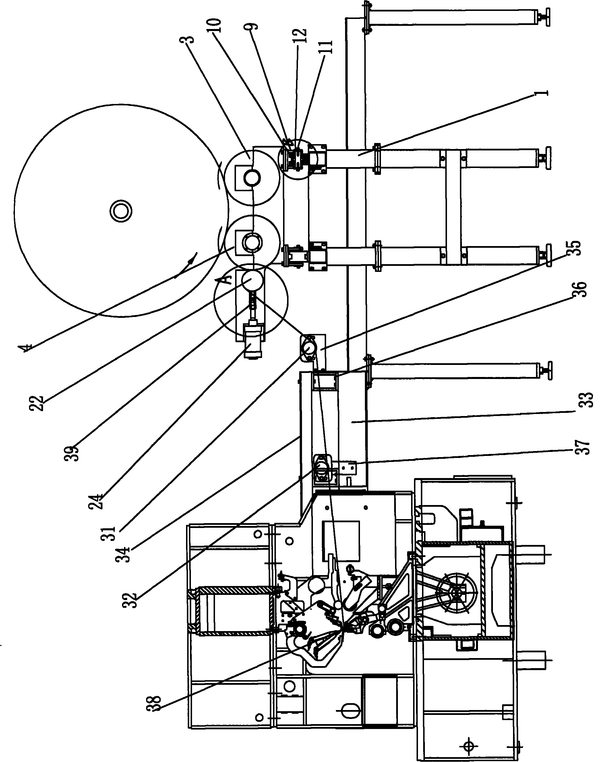
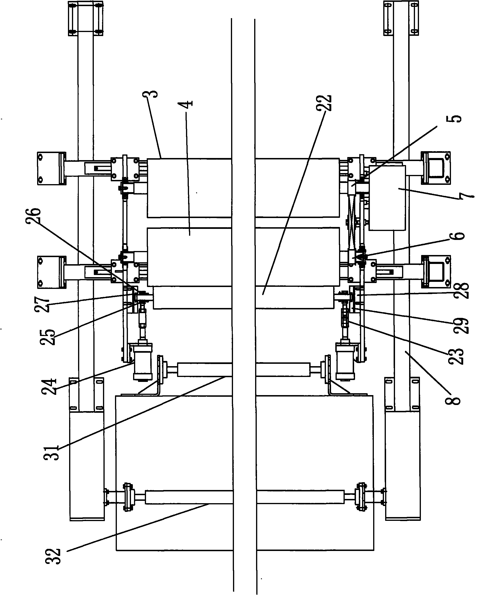
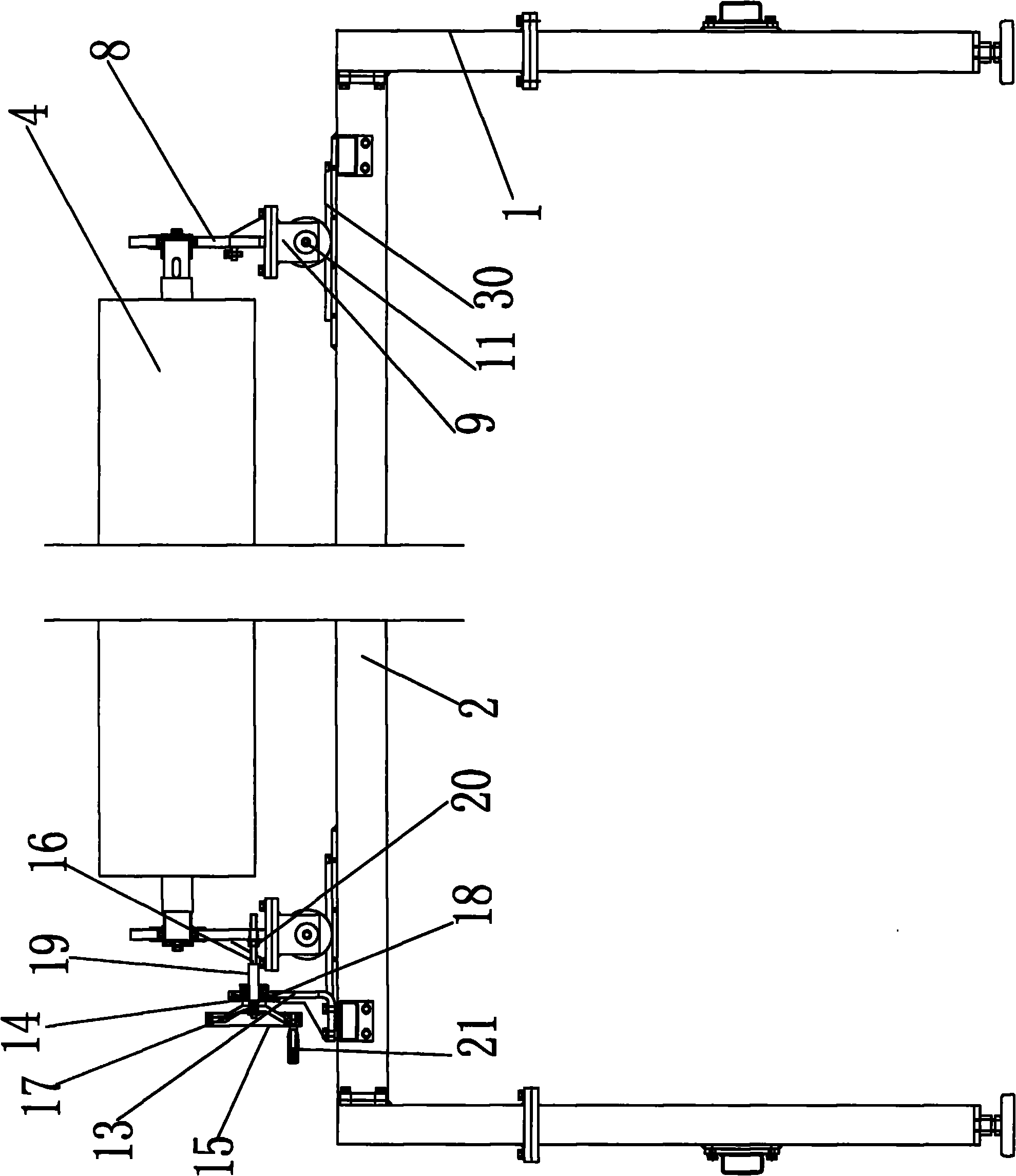
[0018] See attached Figure 1 to Figure 5 A kind of warp knitting machine unwinding device shown, it comprises fixed mount 1, crossbeam 2 and the unwinding device that is arranged on crossbeam 2, and this friction unwinding device comprises active unwinding roller 3, driven unwinding roller 4, The active synchronous pulley 5 that controls the rotation of the active unwinding roller 3, the driven synchronous pulley 6 that controls the rotation of the driven unwinding roller 4, the active synchronous pulley 5 and the driven synchronous pulley 6 are connected with the motor transmission 7, and the active The unwinding roller 3 and the driven unwinding roller 4 are arranged on the unwinding roller fixing plate 8 . In order to make the cloth surface after unwinding correspond to the position of the knitting position of the warp knitting machine and improve the knitting quality, an unwinding roller position adjustment device is arranged under the unwinding roller fixing plate 8, whi...


PUM


Abstract

The invention discloses an unwinding device for a warp knitting machine. The unwinding device for the warp knitting machine comprises a fixed frame, a cross beam and an unwinding device, wherein the unwinding device is arranged on the cross beam; the frictionally unwinding device comprises a driving unwinding roll, a driven unwinding roll, a driving synchronous belt wheel and a driven synchronous belt wheel; the driving synchronous belt wheel is used for controlling the rotation of the driving unwinding roll; the driven synchronous belt wheel is used for controlling the rotation of the driven unwinding roll; the driving synchronous belt wheel and the driven synchronous belt wheel are connected with a motor driving device; and the driving unwinding roll and the driven unwinding roll are arranged on an unwinding roll fixing plate. The unwinding device for the warp knitting machine has the advantages of guaranteeing the constant-speed unwinding of a cloth roll during unwinding, adjusting the position of cloth conveniently, pressing the unwound cloth flatly and improving the knitting quality of the warp knitting machine.

Description

technical field [0001] The invention relates to the technical field of textile machinery, in particular to a warp knitting machine unwinding device. Background technique [0002] At present, existing warp knitting machine unwinding devices generally adopt the central shaft unwinding method, that is, the cloth roll of gray cloth is arranged on the central shaft, and then the central shaft is driven by a motor to rotate to unwind the cloth roll. When this unwinding method is unwinding, the central axis must bear the full weight of the cloth roll, which is easy to bend or even break under heavy pressure. Moreover, when unwinding, the central axis and the cloth roll are prone to slipping, that is, the central axis rotates. However, the cloth roll cannot follow the rotation, which affects the effect of unwinding. Contents of the invention [0003] The object of the present invention is to provide a warp knitting machine unwinding device for the problem of poor unwinding effect...

Claims


Application Information

Patent Timeline
Patent Type & Authority Applications(China)
IPC IPC(8): D04B27/34
Inventor 谈昆伦陈震凌伯明陈龙谈良春
Owner CHANGZHOU DIBA TEXTILE MACHINERY
Learn More