Water treatment device integrating functions of clarification, air flotation and ultrafiltration
A water treatment device and air flotation technology, applied in flotation water/sewage treatment, osmosis/dialysis water/sewage treatment, flocculation/sedimentation water/sewage treatment, etc., can solve the problems of long treatment process and high operating cost, and achieve Low operating cost, mitigation of membrane fouling, and wide application range
- Summary
- Abstract
- Description
- Claims
- Application Information
AI Technical Summary
Problems solved by technology
Method used
Image
Examples
specific Embodiment approach 1
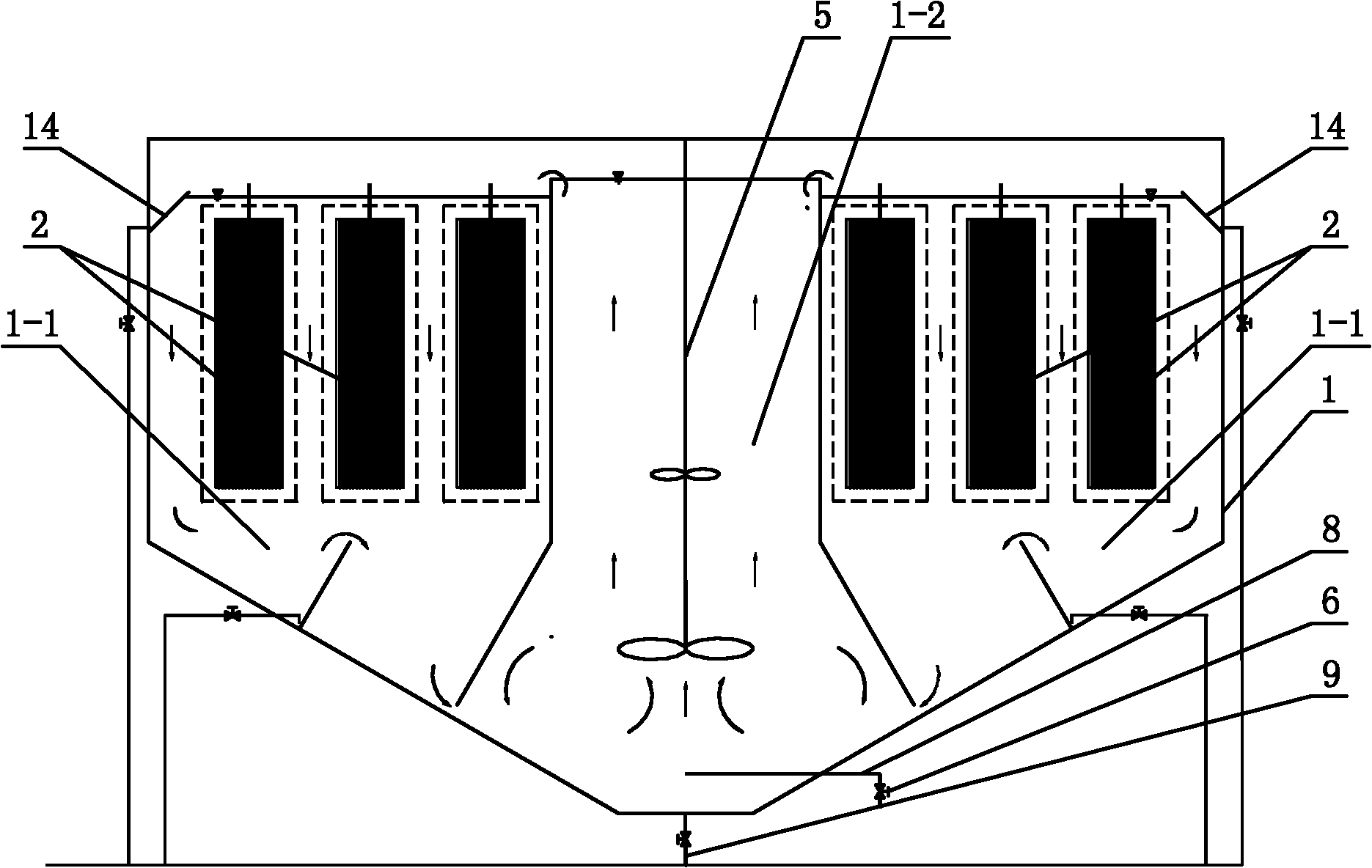
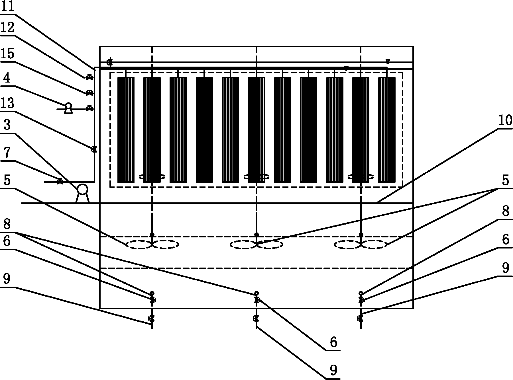
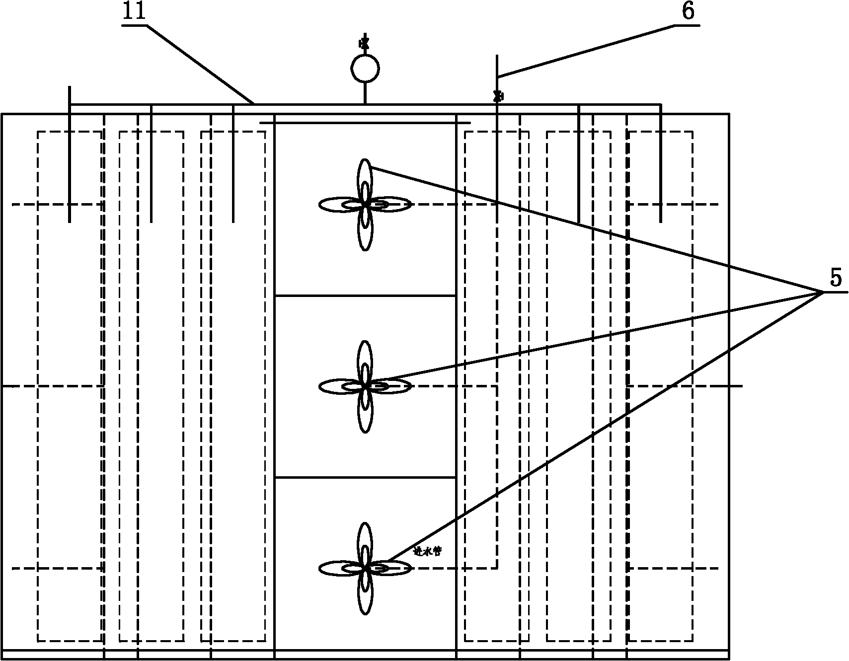
[0012] Specific implementation mode one: as Figure 1~6 As shown, a water treatment device integrating clarification, air flotation and ultrafiltration described in this embodiment includes a pool body 1, an ultrafiltration membrane module 2, a rotor suction pump 3, a vacuum pump 4, and a water production valve 7 , aeration pipe 10, water production pipe 11, air inlet pipe 12, water inlet valve 13, a plurality of turbine agitators 5, a plurality of water inlet pneumatic valves 6, a plurality of water inlet pipes 8 and a plurality of vent pipes 9, the pool Two separation areas 1-2 are arranged symmetrically on both sides of the body 1. The middle part of the pool body 1 is a coagulation area 1-1, and the water inlet pipe 8 and the vent pipe 9 are respectively connected to the bottom of the coagulation area 1-1. The pool body 1 is connected, and each water inlet pipe 8 is provided with a water inlet pneumatic valve 6. The water production pipe 11 is connected with the ultrafiltr...
specific Embodiment approach 2
[0013] Specific implementation mode two: as figure 1 and Figure 4 As shown, the water treatment device in this embodiment also includes two V-shaped drainage grooves 14, the cross section of which is V-shaped, and the two V-shaped drainage grooves 14 are symmetrically arranged on both sides of the pool body 1. on the side wall, and are all arranged parallel to the length direction of the ultrafiltration membrane module 2. So set, the V-shaped drainage groove 14 can collect and discharge the waste water on the surface during backwashing. Other compositions and connections are the same as in the first embodiment.
specific Embodiment approach 3
[0014] Specific implementation mode three: as figure 2 and Figure 5 As shown, the water treatment device in this embodiment further includes a maintenance liquid pipe 15 , and the maintenance liquid pipe 15 is arranged on the water production pipe 11 and located between the air inlet pipe 12 and the vacuum pump 4 . Such setting facilitates the maintenance cleaning of the membrane system. Other compositions and connections are the same as those in Embodiment 1 or Embodiment 2.
[0015] Specific implementation mode four: as figure 2 , image 3 and Figure 5 As shown, the number of turbine agitators 5 in this embodiment is three. With such an arrangement, coagulation and stirring can be carried out and the water flow can be pushed forward, so as to promote the water circulation in the coagulation zone and the separation zone. Other compositions and connections are the same as those in the third embodiment.
[0016] Specific implementation mode five: as figure 2 and ...
PUM
 Abstract
Description
Claims
Application Information
 - R&D
- Intellectual Property
- Life Sciences
- Materials
- Tech Scout
- Unparalleled Data Quality
- Higher Quality Content
- 60% Fewer Hallucinations
Browse by: Latest US Patents, China's latest patents, Technical Efficacy Thesaurus, Application Domain, Technology Topic, Popular Technical Reports.
© 2025 PatSnap. All rights reserved.Legal|Privacy policy|Modern Slavery Act Transparency Statement|Sitemap|About US| Contact US: help@patsnap.com


