
Parking brake system

A parking brake and brake equipment technology, applied in the direction of brake safety systems, brakes, brake transmissions, etc., can solve the problems that end users are not satisfied with the overall control, and do not provide electromechanical gradual application or release, etc., to achieve effective Contributes to fuel, prolongs life, and reduces power consumption

Inactive Publication Date: 2010-12-22
GM GLOBAL TECH OPERATIONS LLC
View PDF6 Cites 2 Cited by
  • Summary
  • Abstract
  • Description
  • Claims
  • Application Information

AI Technical Summary

Problems solved by technology

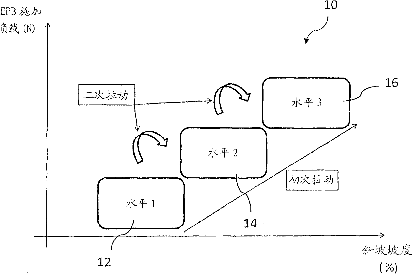
[0005] Although electromechanically-operable parking brake systems provide a large number of functions, such as automatic or semi-automatic activation and release modes, end users are still dissatisfied with the overall operation of such parking brakes because these systems do not provide control over electromechanically-operable parking brakes. Dynamic manual and / or gradual application or release

Method used


Image

  • Parking brake system
  • Parking brake system
  • Parking brake system

Examples


Embodiment Construction

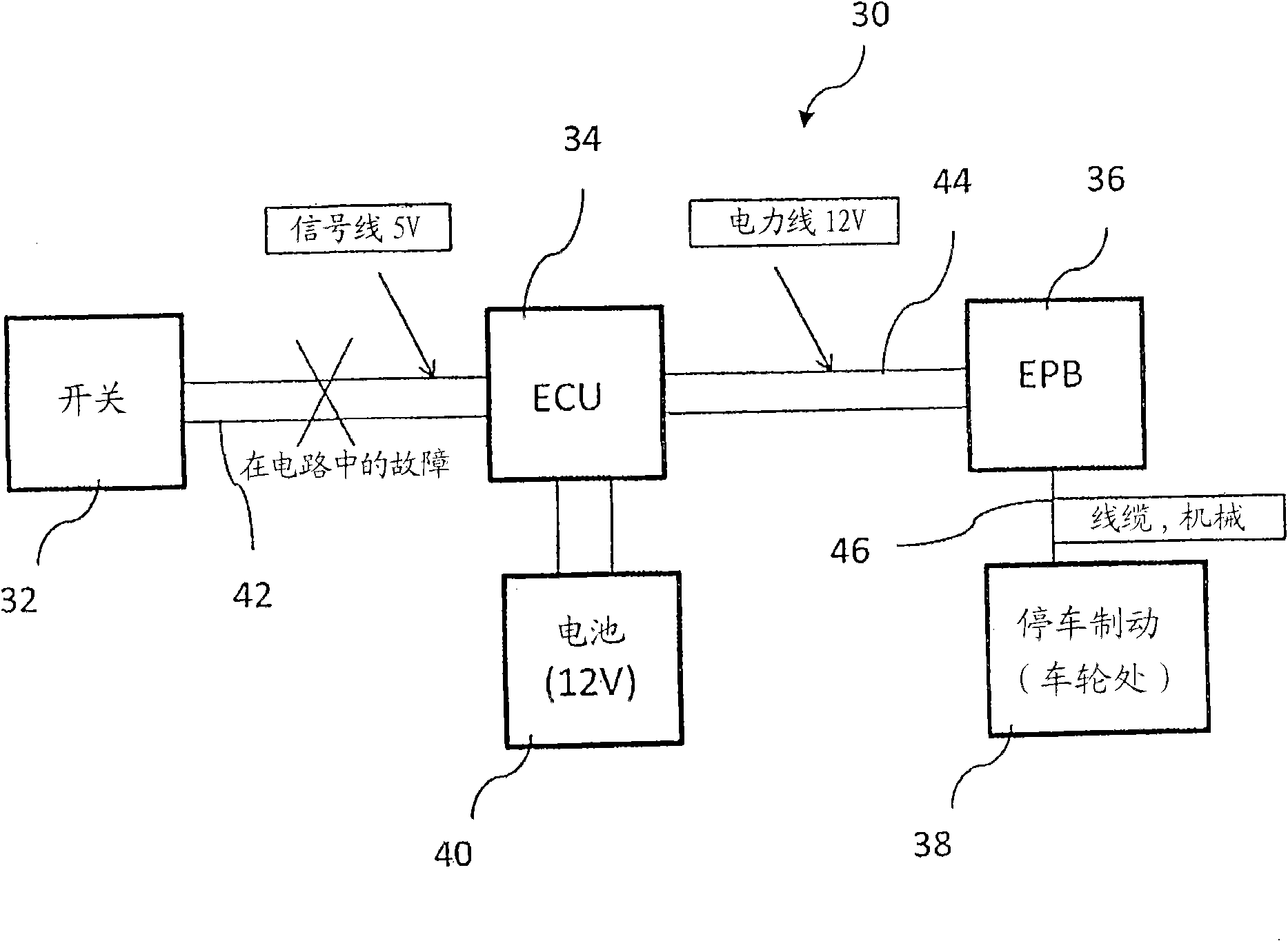
[0048] electromechanically operable parking brake system 30, as in image 3 As shown in the block diagram of , the braking device 38 is included, which normally interacts with the brake disc or drum of the wheel. The braking device 38 may include brake calipers to transmit braking forces to respective wheels.

[0049] The brake apparatus 38 is mechanically coupled to the brake module 36 by a force transmission system 46 , for example by a Bowden cable or similar mechanical force transmission device. The brake module 36 is adapted to generate sufficient brake application force in response to corresponding control signals generated by the electronic control unit 34 . The control unit 34 and the brake module 36 are electrically coupled by a power line 44 . The control unit 34 thus acts as a switch for feeding the braking module 36 with electrical energy provided by a power source, such as the battery 40 . The control unit 34 also provides the connection of the control side and...


PUM


Abstract

The invention relates to an electromechanically operable parking brake system for motor vehicles and a corresponding operation method, wherein at least one brake device (38) is lockable by a brake module (36), a control unit (34) is electrically coupled to the brake module (36) and is further adapted to generate a first control signal for generating a first brake application force, and wherein a safeguard mechanism is adapted to generate a second control signal for applying a second brake application force, wherein the second brake application force is larger in magnitude than the first brake application force.

Description

technical field [0001] The invention relates to the field of electromechanically operable parking brake systems for motor vehicles, as well as motor vehicles equipped with such parking brake systems. The invention also relates to a method of operating an electromechanically operable parking brake system. Background technique [0002] In an electromechanically operable parking brake system, a drive means, typically in the form of an electric motor, is adapted to apply a load to the brake module. The magnitude of the load or brake application force provided by such a brake module must be within a range in which the vehicle is sufficiently immobilized against unintended movement. [0003] In many electromechanically-operable parking brake systems, the parking brake is activated and / or released by the depression of a corresponding parking brake button or switch. When applied, the electromechanical driver, the braking module, typically produces the maximum applied load to the b...

Claims


Application Information

Patent Timeline
Patent Type & Authority Applications(China)
IPC IPC(8): B60T8/17B60T13/74B60T17/22
CPCB60T13/746
Inventor 马格努斯·古斯塔夫森斯蒂芬·桑德罗比·坎农
Owner GM GLOBAL TECH OPERATIONS LLC
Learn More