
Device and method for detecting sanding critical flow velocity of gas well

A critical flow rate, gas well technology, used in the measurement of fluid velocity by differential pressure, measurement devices, and the use of cyclone flowmeters to measure fluid velocity, etc.

Inactive Publication Date: 2010-12-15
CHINA UNIV OF PETROLEUM (BEIJING)
View PDF4 Cites 13 Cited by
  • Summary
  • Abstract
  • Description
  • Claims
  • Application Information

AI Technical Summary

Problems solved by technology

The cost of using field tests is too high, and it will cause some damage to the formation near the wellbore; theoretical formulas can only be used to roughly estimate, and the error is large; laboratory tests mostly use small cores for one-dimensional linear flow displacement, which is not representative, and is consistent with the real diameter. There is a certain difference in seepage characteristics
The full-diameter rock core radial permeability measuring instrument that has been used has similarities with the present invention, but its gas source is too small to make the core reach the critical flow rate of sand production, and there is no filter device at the outlet, so it is impossible to identify whether sand is produced
At present, the petroleum industry has not formed a mature device and method for measuring the critical flow rate of sand production in gas wells. Therefore, in order to reasonably determine the production pressure difference and production allocation, it is urgent to develop a device and method for measuring the critical flow rate of sand production in gas wells to guide On-site production

Method used


Image

  • Device and method for detecting sanding critical flow velocity of gas well
  • Device and method for detecting sanding critical flow velocity of gas well
  • Device and method for detecting sanding critical flow velocity of gas well

Examples


specific Embodiment

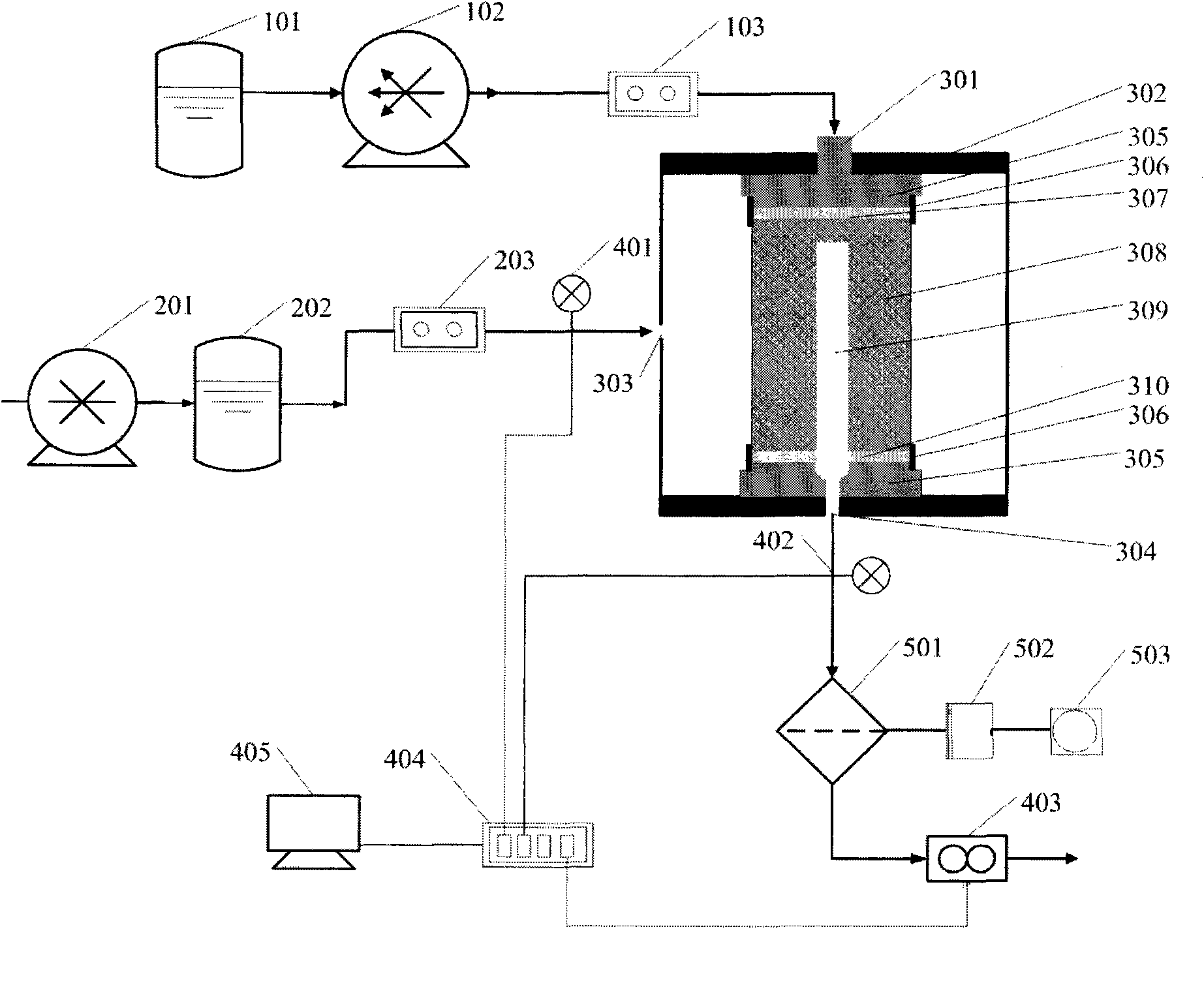
[0023] 1) According to figure 1 As shown in the schematic diagram, connect the axial pressurization system, gas supply system, simulation system, measurement and collection system, sand treatment system, and check the tightness of each component and pipeline;

[0024] 2) A rubber gasket 307 is placed on the end face of the full-diameter rock core 308 without holes, and then a self-adhesive sealing tape 306 is used to seal the upper pressure head of the full-diameter rock core 308, the rubber gasket 307 and the core holder 305; the full-diameter rock core 308 is perforated A rubber gasket 310 with holes is placed on the end face, and the aperture of the rubber gasket 310 is equal to or slightly larger than the diameter of the hole 309 in the core, and then the full-diameter core 308, the rubber gasket 310 and the core holder 305 are pressed down using a self-adhesive sealing tape 306 head; the following table 1 shows the full-diameter core size table after drilling and coring p...


PUM


Abstract

The invention provides a device and a method for detecting the sanding critical flow velocity of a gas well. The device consists of an axial compression system, a gas supply system, a simulation system, a measuring and acquiring system and a sand processing system. The method comprises the following steps of: providing different supply pressure for the simulation system simulating the production state of the gas well by using the gas supply system; measuring parameters such as inlet pressure, outlet pressure, gas flow rate, sand production volume after a certain experimental time and the like to obtain the sanding critical flow rate through a test result; and combining the sanding critical flow rate with the rock core size to solve the sanding critical flow velocity. Thus, the technology for determining the sanding critical flow velocity of the gas well on site is provided. By adopting the device and the method of the invention, as the experimental conditions are similar to the geological conditions of gas pools, the problem of detecting the sanding critical flow velocity under the condition of open hole completion of the gas well is solved accurately, conveniently and economically, and an experimental evidence is provided for directing on-site production of the gas pools.

Description

technical field [0001] The invention relates to a test device for measuring the critical velocity of sand production in a gas well, and also relates to a method for applying the test device. Background technique [0002] For unconsolidated sandstone gas reservoirs, in order to increase the production of gas wells, it is necessary to increase the production pressure difference and increase the flow rate of natural gas in the gas wells, resulting in different degrees of sand production in the gas wells. With the continuation of development, the number of wells producing sand is increasing, and the situation of sand production is becoming more complicated and intensified. Sand production in gas wells shortens the production cycle, reduces production, and even shuts down or scraps gas wells, seriously restricting the potential of gas wells. At the same time, it also rapidly deteriorates mining equipment and surface technology, seriously affecting the efficient and stable product...

Claims


Application Information

Patent Timeline
IPC IPC(8): G01P5/14G01P5/01G01M10/00
Inventor 邓金根李萍范永涛王利华刘书杰曹砚峰
Owner CHINA UNIV OF PETROLEUM (BEIJING)
Learn More