Power supply door lock device

A technology of door locks and power supply seats, which is applied in the direction of circuit devices, building locks, electrical components, etc., can solve problems such as power line breakage, troublesome wire installation, and easy coordination problems, and achieve fatigue life avoidance, beautiful appearance, and structural integrity. compact effect

Inactive Publication Date: 2010-12-15
吴斐
View PDF4 Cites 0 Cited by
  • Summary
  • Abstract
  • Description
  • Claims
  • Application Information

AI Technical Summary

Problems solved by technology

Existing electronic door locks are divided into electronic door locks with batteries and independent power supply and electronic door locks with external power supply lines. Although the structure of electronic door locks without batteries can be made smaller and more compact, the wires for power supply The installation is very troublesome, and the power cord needs to be wound on the door, which affects the appearance. After long-term use, the power cord is easily broken due to fatigue and damage caused by the back and forth rotation of the door, causing failures, causing great inconvenience and safety hazards to users.
[0003] Therefore, a wireless power supply device based on the electromagnetic induction principle of an electromagnetic coil emerges at the historic moment. Most of the existing wireless power supply devices have complex structures, and their structures use spring-supported contact keys to achieve close contact. , with the aging of the spring, it is easy to have problems with the coordination; and this elastic contact key needs to be installed with a spring, which has many parts and troublesome installation, and the protruding elastic contact key affects the appearance of the product. Therefore, it is necessary to design a structure more Optimize existing structures for compact wireless power supply units

Method used


Image

  • Power supply door lock device
  • Power supply door lock device
  • Power supply door lock device

Examples


Embodiment Construction

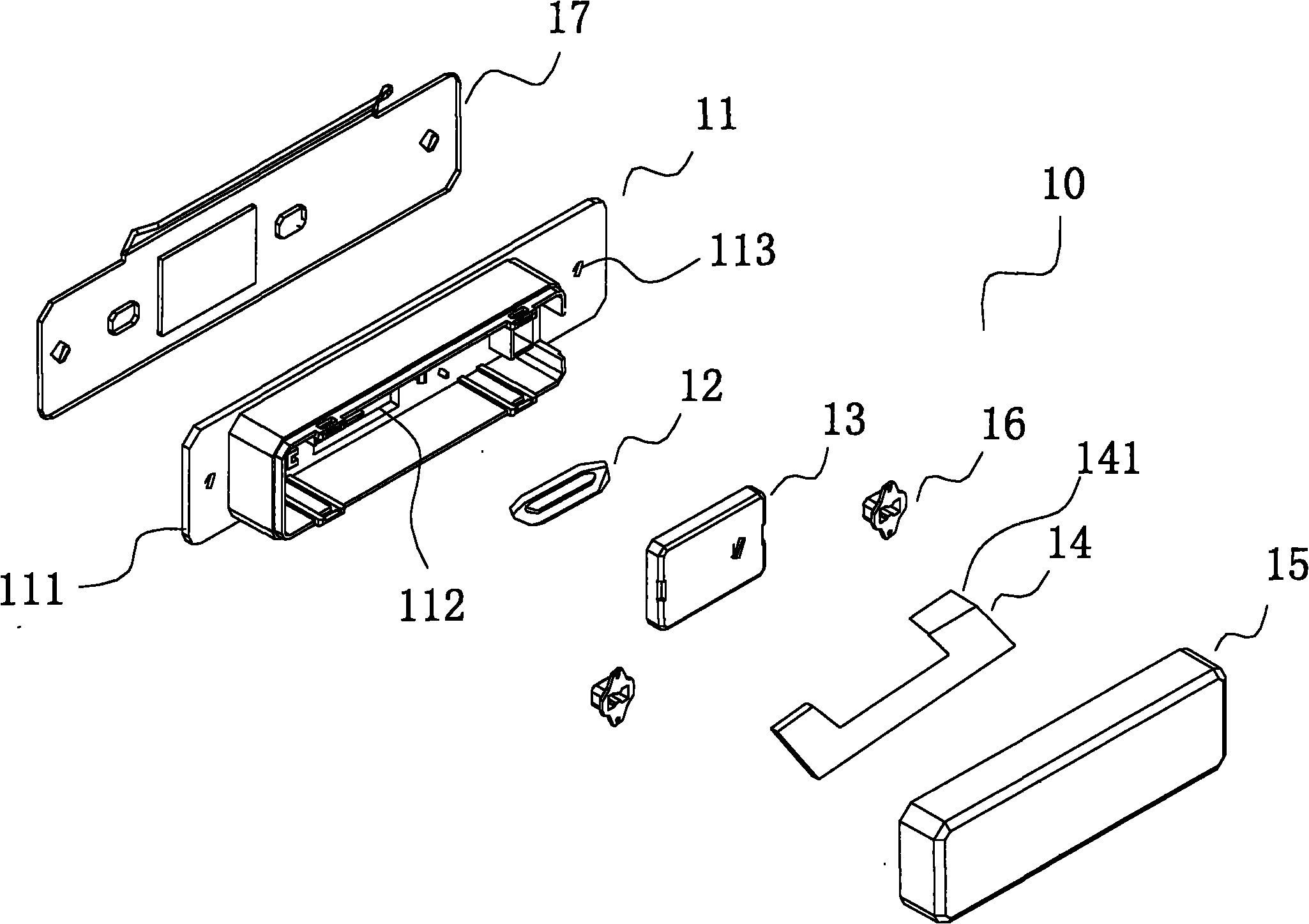
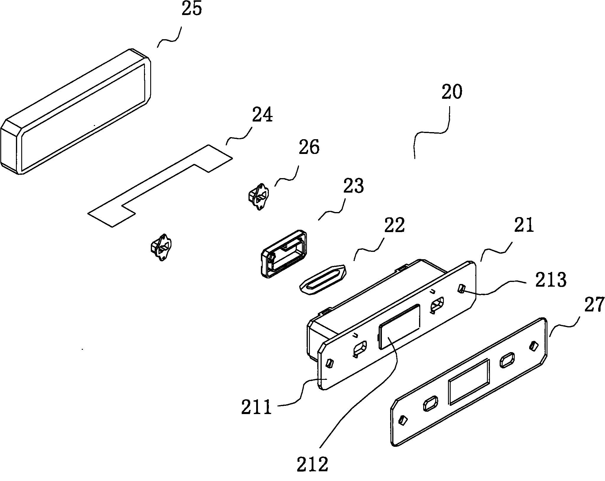
[0017] Such as Figure 1-4 As shown, the present invention includes a power supply seat 10 installed on the door frame and a power take-off seat 20 correspondingly installed on the rotating edge of the door;

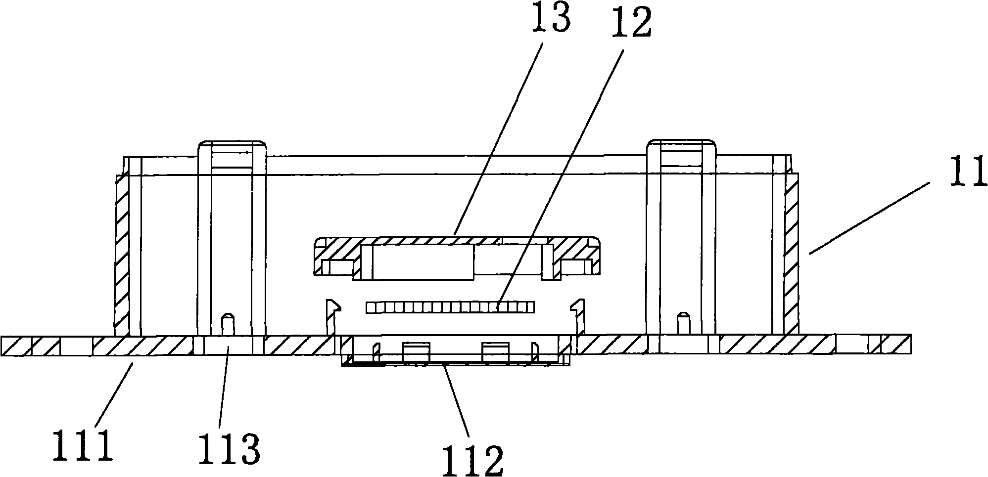
[0018] The power supply seat includes a power supply seat box 11, a power supply electromagnetic coil 12, a power supply coil pressure plate 13, a power supply circuit board 14 and a power supply seat rear cover 15, the power supply seat box 11 is made of plastic material, and the middle part of the power supply box panel 111 is provided with The power supply contact panel 112, the power supply contact panel 112 and the power supply seat box panel 111 are integrally injection molded, and the thickness of the power supply contact panel 112 is 111 degrees thinner than the thickness of the power supply seat box panel, and the inside of the power supply contact panel 112 is equipped with a fixed power supply through the power supply coil pressure plate 13 The electromagnetic...


PUM


Abstract

The invention relates to a power supply door lock device. In the invention, a power supply electromagnetic coil in a power supply seat generates an alternating magnetic field by utilizing external alternating power supply equipment; when a gate is closed, the alternating magnetic field acts on a power taking induction closing coil in a power taking seat; because the magnetic flux in the power taking induction closing coil changes continuously, the power taking induction closing coil produces induction current; and the induction current charges a charging circuit in an electronic door lock. Because a power taking contact panel and a power taking seat panel adopted by the invention are integrally formed by injection molding, an attractive appearance can be achieved; the power taking seat panel is thin, so the power taking electromagnetic coil on the inner side of the power taking seat panel can conveniently induce the magnetic field; the structure has the advantages of a few components, simple assembly and low cost; meanwhile, the power supply seat is also designed in the same way. Thus, compared with the conventional similar products, the device has the characteristics of compact structure, a few components, simple assembly, low cost and attractive appearance and overcomes the disadvantages such as fatigue life and the like caused by using an elastic contact key of a spring in the prior art.

Description

technical field [0001] The invention relates to the technical field of accessories related to electronic door locks, in particular to a power supply door lock device with compact structure and beautiful appearance, which adopts wireless electromagnetic induction technology to supply power to electronic door locks. Background technique [0002] With the development of locksets, more and more electronic door locks are widely used in hotels, guesthouses, families and other occasions. Existing electronic door locks are divided into electronic door locks with batteries and independent power supply and electronic door locks with external power supply lines. Although the structure of electronic door locks without batteries can be made smaller and more compact, the wires for power supply Installation is very troublesome, and the power cord needs to be wound on the door to affect the appearance. After long-term use, the power cord is easily broken due to fatigue and damage caused by ...

Claims


Application Information

Patent Timeline
IPC IPC(8): E05B47/02E05B17/00H02J17/00H02J50/10
Inventor 吴斐
Owner 吴斐
Why Eureka
Try Eureka