Delay locking method, delay locking device and anti-theft lock
A delay locking and delay control technology, applied in the field of anti-theft locks, can solve the problems of unsatisfactory and unsatisfactory anti-theft effects, and achieve the effects of short production and testing time, exquisite design and strong versatility
Inactive Publication Date: 2010-12-15
丁汉云
View PDF8 Cites 8 Cited by
- Summary
- Abstract
- Description
- Claims
- Application Information
AI Technical Summary
Problems solved by technology
For example, under the long-term attack of a lock matching master, the anti-theft effect is not ideal.
With the simple combination of the two technologies, although the anti-theft effect can be improved, it is still not satisfactory.
Method used
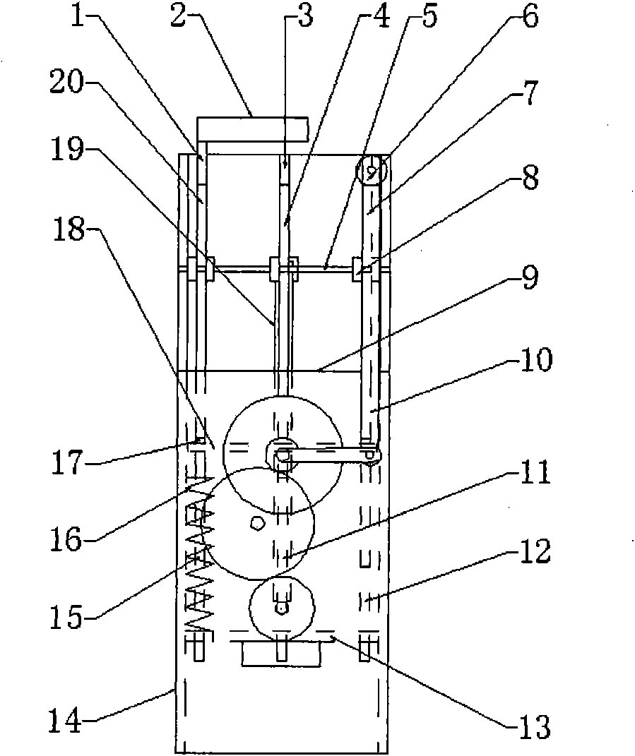
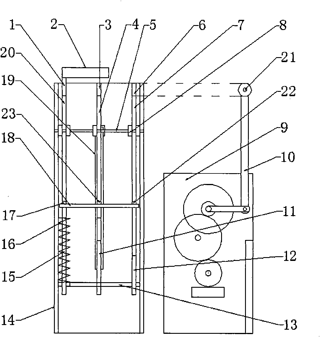
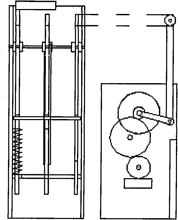
View moreImage
Smart ImageViewing Examples
Examples
Embodiment Construction
[0015] The present invention can be embodied according to the techniques described in the Summary of the Invention, and the following non-limiting examples are used to further illustrate the implementation mode.
Login to View More PUM
 Abstract
The invention relates to a delay locking method, a delay locking device and an anti-theft lock, and belongs to the field of locks. The extension and retraction of a locking contact is controlled by a delay control device and the unlocking and locking of a lock cylinder marble is controlled by the locking contact so as to fulfill the aim of delay locking. The device is characterized in that: when an unlocking guard plate is unlocked or after an unlocking command is triggered, the delay control device drives the locking contact to return and unlock the lock cylinder marble in a locked state through a transmission device, a cylinder of a lock can be unlocked by a key in certain time, namely delay time set by the delay control device; the delay control device drives the locking contact to lock the lock cylinder marble in an unlocked state through the transmission device after the delay time is out; if the previous key is still in the lock at the time, the key can control the unlocking andlocking of the lock, and if the key is inserted again, the key cannot unlock the cylinder; and the delay control device comprises a mechanical delay control device or an electronic delay control device. If the key is unlocked in a theft mode, the time for manufacturing and testing the theft key is extremely short, the lock is difficult to unlock, and the anti-theft effect is obviously enhanced.
Description
technical field [0001] The invention relates to a time-delay locking method, a time-delay locking device for realizing the method, and an anti-theft lock using the time-delay locking device, belonging to the field of locks for fixing buildings. Background technique [0002] Existing locksets, such as door locks and motorcycle locks, are generally composed of a lock body, a lock cylinder, a transmission mechanism, and a switch device (such as a lock head). , the hole in the lock body is provided with a pin slot corresponding to the position of the pin, and the transmission mechanism is connected with the lock cylinder and the switch device. With the improvement of anti-theft technology, anti-theft locks using electricity, magnetism, sound, light, and passwords have been widely used on doors, bicycles, automobiles, safes, etc., such as: the name "An anti-theft lock that can delay alarm" 》, application number CN95235157.9, when any object enters the keyhole for unlocking, if t...
Claims
Login to View More Application Information
Patent Timeline
 Patent Type & Authority Applications(China)
IPC IPC(8): E05B27/00E05B47/00E05B15/00
Inventor 丁汉云
Owner 丁汉云
Features
- R&D
- Intellectual Property
- Life Sciences
- Materials
- Tech Scout
- Unparalleled Data Quality
- Higher Quality Content
- 60% Fewer Hallucinations
Learn More Browse by: Latest US Patents, China's latest patents, Technical Efficacy Thesaurus, Application Domain, Technology Topic, Popular Technical Reports.
© 2025 PatSnap. All rights reserved.Legal|Privacy policy|Modern Slavery Act Transparency Statement|Sitemap|About US| Contact US: help@patsnap.com


