
Method and system for continuous or semi-continuous laser deposition

A laser deposition, semi-continuous technology, applied in the direction of ion implantation plating, metal material coating process, coating, etc., can solve the problems of low control level of ablation process and hindering high quality

Inactive Publication Date: 2010-12-08
OTB SOLAR
View PDF1 Cites 6 Cited by
  • Summary
  • Abstract
  • Description
  • Claims
  • Application Information

AI Technical Summary

Problems solved by technology

A problem associated with known methods is the relatively low level of control over the ablation process, which prevents the formation of high quality films

Method used


Image

  • Method and system for continuous or semi-continuous laser deposition
  • Method and system for continuous or semi-continuous laser deposition

Examples


Embodiment Construction

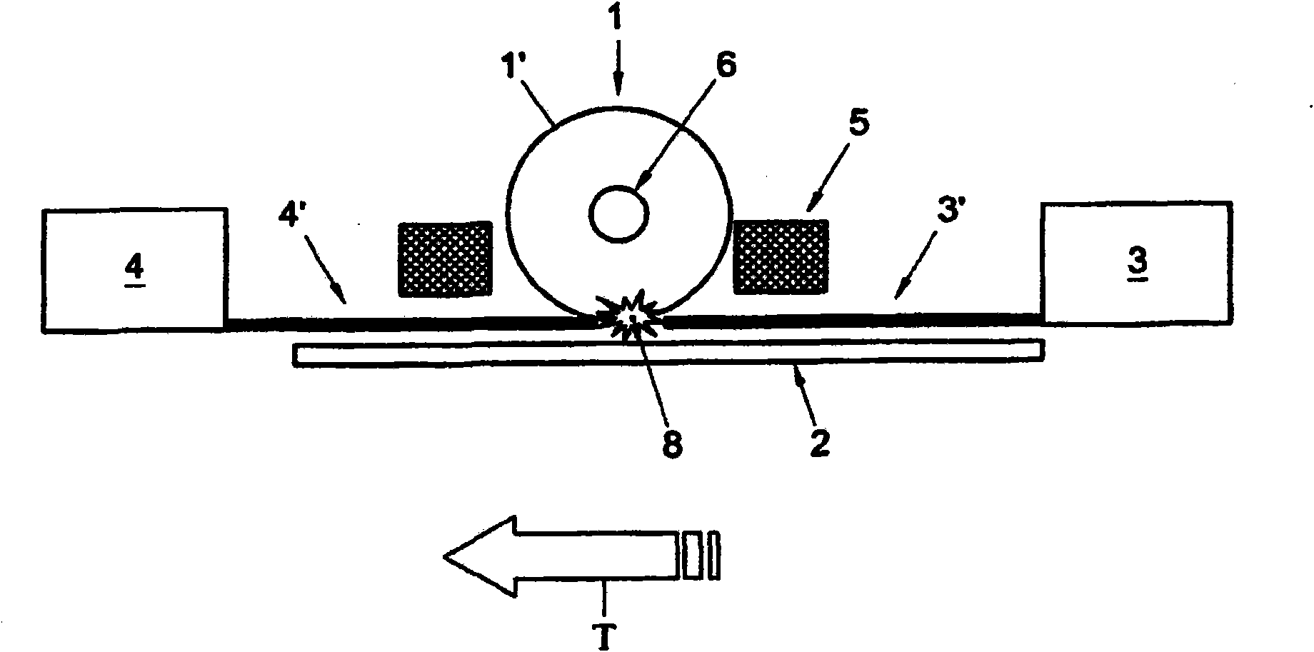
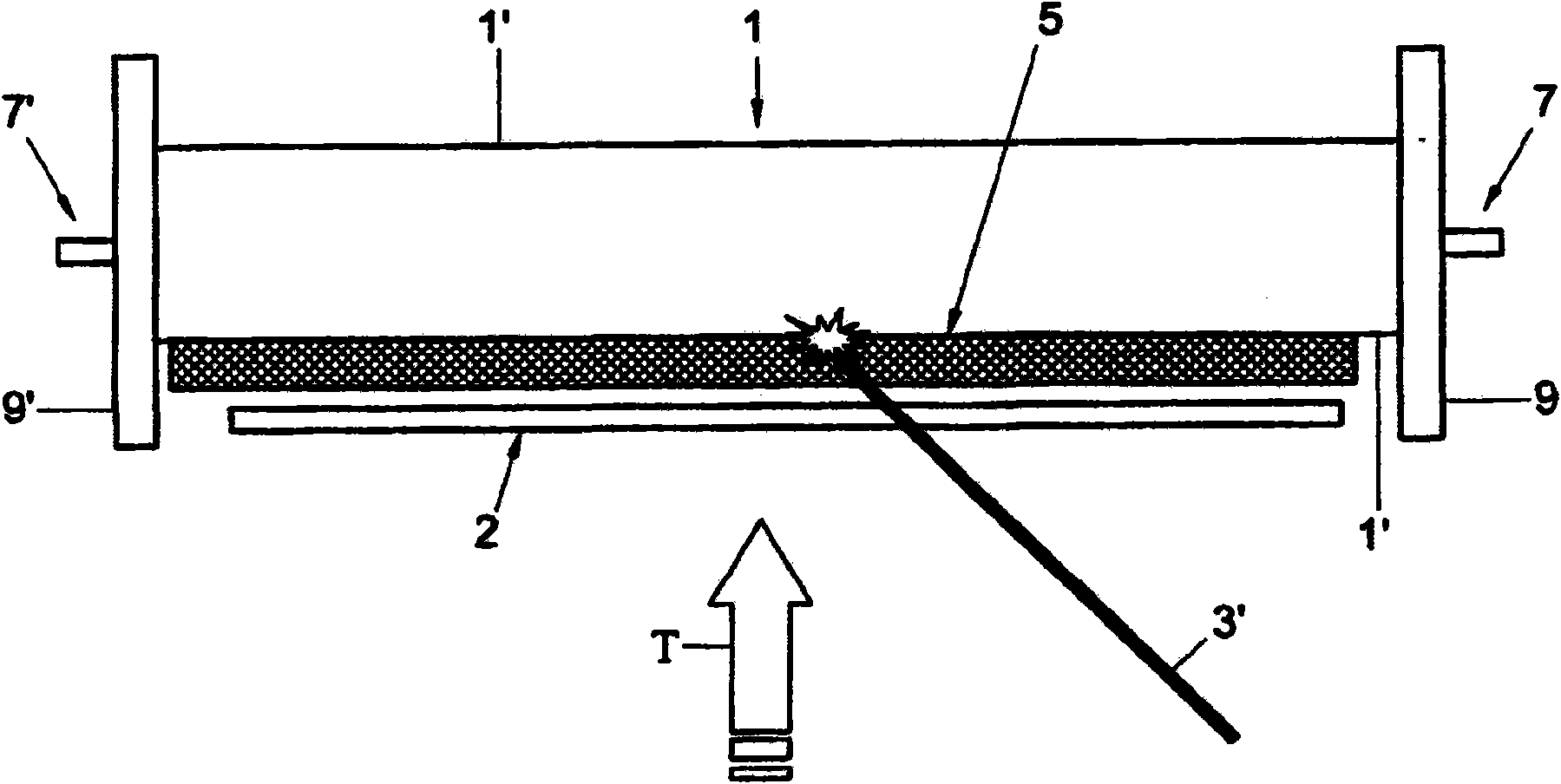
[0018] figure 1 and figure 2 A laser deposition system according to the invention is shown. The figures show the following elements: a cylindrical target 1 with a target surface 1' provided with an internal fluid channel 6 with end connectors 7 and 7'; in the direction of transport T A moving substrate 2; a first continuous or semi-continuous laser 3 emitting a laser beam 3'; a second laser 4 emitting a laser beam 4'; a gas or plasma gas environment 5, a cloud of laser evaporated material 8, and two Shields 9, 9'. The aforementioned target 1, substrate 2 and gas or plasma gas environment 5 are located within a deposition chamber (also not shown) which is evacuated to sub-atmospheric pressure by means of a pump (not shown) . The lasers 3, 4 do not have to be located inside the deposition chamber; they can also be located outside the deposition chamber, whereby the resulting laser beams 3', 4' travel through one or more transparent windows into the deposition chamber. Such...


PUM


Abstract

The invention relates to a method for deposition of material by laser evaporation wherein the employed laser is a continuous or semi-continuous laser. Using such a laser, it is possible to evaporate the target material in a controlled manner from a local pool of liquid or fluidized target material at the target surface. The invention also provides a system for executing said method.

Description

technical field [0001] The present invention relates to methods and systems for depositing materials by laser evaporation. The method includes providing a first laser, providing a deposition chamber, providing a target of substantially laser evaporated material within the deposition chamber, providing a substrate within the deposition chamber, evacuating the deposition chamber to a low operating said first laser such that a first laser beam is directed at a target so as to form a cloud of laser evaporated material at atmospheric pressure, said substrate is disposed at least partially within said cloud of laser evaporated material, and said The laser evaporated material is deposited on the substrate. Background technique [0002] Such methods are known, for example, from US 2004 / 0033702-A1. A problem associated with known methods is the relatively low level of control over the ablation process, which prevents the formation of high quality films. For example, according to k...

Claims


Application Information

Patent Timeline
Patent Type & Authority Applications(China)
IPC IPC(8): C23C14/28
CPCC23C14/28C23C14/562
Inventor 弗朗西斯库斯·科尔内留斯·丁斯沃特鲁斯·约翰内斯·玛丽亚·布罗克
Owner OTB SOLAR
Learn More