Landing beam sliding hydraulic support system for coal mine

A technology of hydraulic support and roof beam, which is used in mine roof support, mining equipment, earthwork drilling and other directions, can solve the problems that uneven roof cannot be effectively supported, and hydraulic support cannot be solved at the same time, so as to improve labor productivity and reduce support. process, the effect of ensuring construction safety

Inactive Publication Date: 2012-05-02
BEIJING CHENGTIAN HENGYE COAL MINE EQUIP CO LTD
View PDF4 Cites 0 Cited by
  • Summary
  • Abstract
  • Description
  • Claims
  • Application Information

AI Technical Summary

Problems solved by technology

[0015] The technical problem to be solved by the present invention is that the existing hydraulic support cannot simultaneously solve the phenomenon of "bow head" of the hydraulic support due to the pressure of the roof during the moving process, cannot provide effective support for the uneven roof, and the hydraulic support is deformed due to uneven pressure And the cumbersome work of moving the frame and other problems
[0016] Furthermore, the present invention also solves the problem of adjusting the moving direction of the hydraulic support according to the roadway during the moving process, and at the same time solves the phenomenon of roof leakage caused by the forward movement of the supports one by one, and realizes full-time monitoring of the roof. Sealed to ensure construction safety

Method used


Image

  • Landing beam sliding hydraulic support system for coal mine
  • Landing beam sliding hydraulic support system for coal mine
  • Landing beam sliding hydraulic support system for coal mine

Examples


Embodiment 1

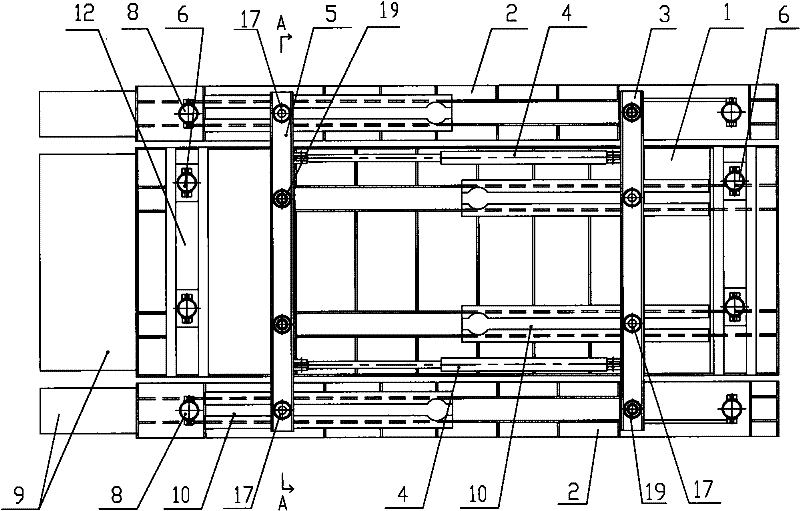
[0060] combine figure 1 As shown, the roof girder sliding hydraulic support system for coal mines includes a main support beam 1, a main beam support device 6 located below the main support beam 1, and side rails placed on both sides of the main support beam 1. The distribution beam 2 and the side beam supporting device 8 placed under the side distribution beam 2 . Below the main supporting beam 1 and the side supporting beam 2, there are side beam connecting beams 3 and main beam connecting beams 5 arranged in parallel. The middle part of the side beam connecting beams 3 is connected to the bottom of the main supporting beam 1 through a sliding connection mechanism 17, and can slide and It does not fall off from the main supporting beam 1; the two ends of the side beam connecting beam 3 are connected to the bottom of the side supporting beam 2 through the movable connection mechanism 19. The middle part of the main beam connecting beam 5 is connected to the bottom of the mai...

Embodiment 2

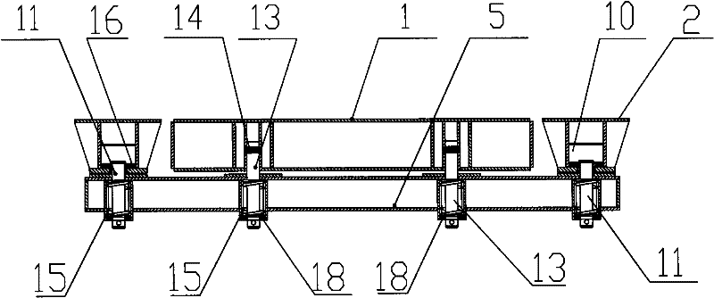
[0077] This embodiment proposes another design scheme of the sliding connection mechanism 17, combining Figure 5 As shown, a boss 20 is arranged on the lower surface of the main support beam 1 (not shown in the figure) and the side distribution beam 2, and the boss 20 is arranged along the length direction of the main support beam 1 and the side distribution beam 2. A pair of rollers 21 are arranged in the track of platform 20, and this roller 21 is connected with main girder coupling beam 5 and side beam coupling beam 3 (not shown in the figure), and can drive main girder coupling beam 5 and side beam coupling beam 3 in convex Slide in the track of platform 20.

[0078] An elastic device 15 is arranged between the main beam connecting beam 5, the side beam connecting beam 3 and the boss 20, and the elastic device 15 can keep the main beam connecting beam 5 and the side beam connecting beam 3 close to the main supporting beam 1 and the Side beam 2. At the same time, it can ...

Embodiment 3

[0080] combine image 3 As shown, the difference between this embodiment and Embodiment 1 is that a fixed side connecting beam 7 is added, and the two ends of the fixed side connecting beam 7 are respectively fixedly connected under one end of the side matching beam 2 . By adding the fixed side connecting beam 7, the combination of the two side matching beams 2 is made more stable, and the integrity and supporting strength of the hydraulic support can be enhanced.


PUM


Abstract

The invention relates to a landing beam sliding hydraulic support system for a coal mine, which comprises a main support beam, a main beam supporting device, side matching beams, side beam supporting devices, a main beam connecting beam and a side beam connecting beam, wherein the middle part of the main beam connecting beam is connected under the main support beam through a movable connecting mechanism and is not disengaged from the main support beam, and both ends of the main beam connecting beam are slidably connected under the side matching beams through slidable connecting mechanisms andare not disengaged from the side matching beams; both ends of the side beam connecting beam are connected under the side matching beams through movable connecting mechanisms and are not disengaged from the side matching beams, and the middle part is connected under the main support beam through a slidable connecting mechanism and is not disengaged from the side matching beams; and the main support beam and the side matching beams interactively move under the traction of a hydraulic control device. The support solves the problems that the traditional hydraulic support can not simultaneously overcome the head drop phenomenon in the support moving process and can not efficiently support uneven top plates, the traditional support deforms due to uniform pressure, the support moving work is complex, and the like.

Description

technical field [0001] The invention relates to a coal mine hydraulic support device, in particular to a combined top beam sliding hydraulic support system. Background technique [0002] The upper and lower ends of the coal mining face and the support along the groove have always been the focus and difficulty of safe coal mining. At present, there are mainly two forms of the end of the coal mining face and the support along the groove at home and abroad: one is the self-moving end Head bracket support, and the second is single-column beam or single-column hinged beam joint support. Among them, the self-moving end support is bulky and heavy, the pedestrian space is small, and transportation and installation are very difficult. Therefore, most coal mines do not use this method or rarely use this method; The protection form is adopted by most coal mines because of its advantages of flexibility, convenience, and low cost. However, the operation procedure of this method is compl...

Claims


Application Information

Patent Timeline
Patent Type & Authority Patents(China)
IPC IPC(8): E21D23/04E21D23/22E21D23/26
Inventor 王洪英徐兴强陈志才石洪起王昱
Owner BEIJING CHENGTIAN HENGYE COAL MINE EQUIP CO LTD
Why Eureka
Try Eureka