Eureka AIR delivers breakthrough ideas for toughest innovation challenges, trusted by R&D personnel around the world.

Overall composite towing beam arching structure for railway steel truss girder cable-stayed bridge

A cable-beam anchoring and composite technology, which is applied in the direction of cable-stayed bridges, bridge forms, bridges, etc., can solve the problems of stress concentration and plastic zone of the anchor plate, achieve compact layout, improve fatigue resistance, and avoid defects Effect

Active Publication Date: 2010-08-04
CHINA RAILWAY ERYUAN ENG GRP CO LTD
View PDF3 Cites 12 Cited by
  • Summary
  • Abstract
  • Description
  • Claims
  • Application Information

AI Technical Summary

Problems solved by technology

The main disadvantage of this anchor structure is that the anchor plate has serious stress concentration near the weld, and it is easy to have a plastic zone at the root of the weld.
[0008] In addition, the above-mentioned cable-beam anchorage structures are all used for steel box girders, but for steel truss girder cable-stayed bridges, the above-mentioned anchorage structures will have greater limitations

Method used


Image

  • Overall composite towing beam arching structure for railway steel truss girder cable-stayed bridge
  • Overall composite towing beam arching structure for railway steel truss girder cable-stayed bridge
  • Overall composite towing beam arching structure for railway steel truss girder cable-stayed bridge

Examples


Embodiment Construction

[0019] The present invention will be further described below in conjunction with the accompanying drawings and embodiments.

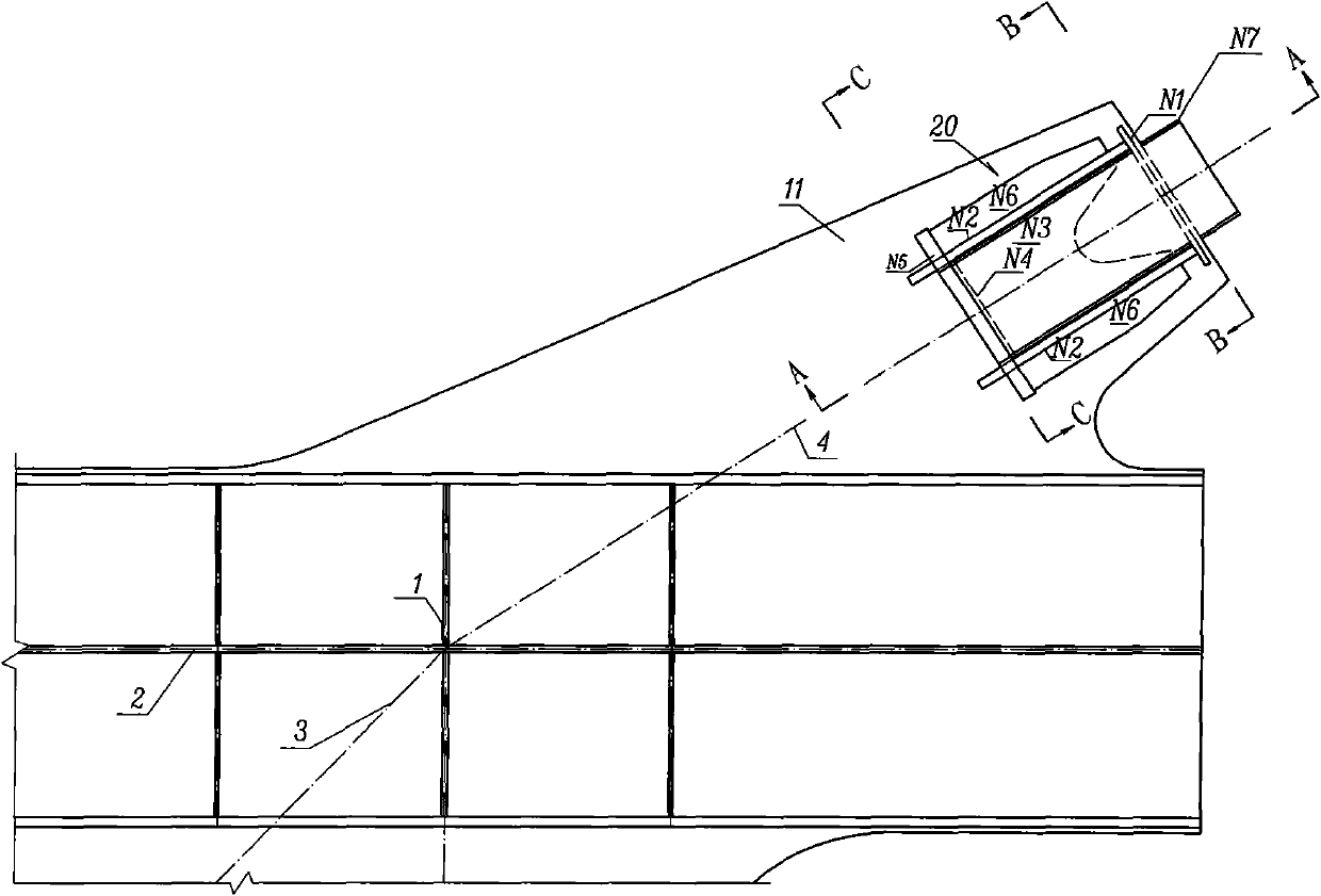
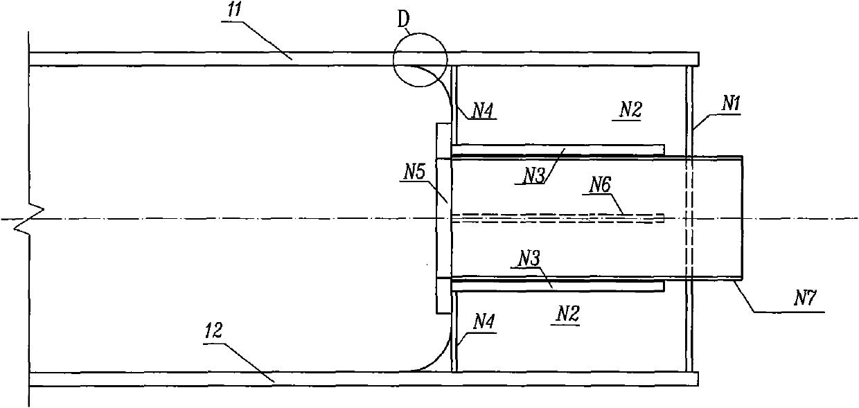
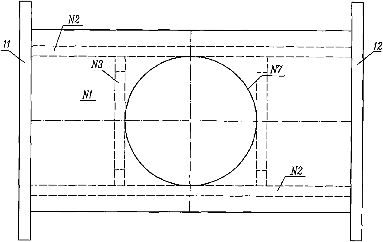
[0020] refer to figure 1 with image 3 , the overall composite cable-girder anchorage structure of the railway steel truss girder cable-stayed bridge of the present invention includes a pair of integral anchor stay plates 11, 12 formed by extending directly upward from the gusset plates on both sides of the upper chord of the main truss, and being arranged on the pair of integral anchor The steel anchor box 20 fixedly connected between the upper parts of the pull plates 11 and 12. That is, the cable-beam anchorage structure is composed of integral anchor stay plates 11, 12 and steel anchor box 20, and the integral anchor stay plates 11, 12 are integrated with the upper chord gusset plate of the main truss, which has good integrity and improves the structural resistance. Fatigue performance effectively overcomes the shortcomings of various existing cab...


PUM


Abstract

The invention discloses an overall composite towing beam arching structure for a railway steel truss girder cable-stayed bridge, which aims to uniformly transfer a cable force to a main truss structure, has high integrity without generating greater stress concentration phenomenon at key parts such as a welding seam and the like, and improves the anti-fatigue performance of the structure. The structure comprises a pair of overall arch plates (11 and 12) and a steel anchor box (20), wherein the pair of overall arch plates (11 and 12) are formed by extending upwards directly from node plates on the two sides of the top chord of a main truss; the steel anchor box (20) is arranged between the upper parts of the pair of overall arch plates (11 and 12) and is fixed with the upper parts of the overall arch plates (11 and 12); a steel sleeve tube (N7) through which a stayed-cable can pass is fixedly arranged in the steel anchor (20); and the stayed-cable axis of the steel sleeve tube (N7) is crossed with the central line (1) of a node of the main truss, an upper chord system line (2) and a diagonal web member system line (3).

Description

technical field [0001] The invention relates to a railway steel truss girder cable-stayed bridge, in particular to a cable girder anchorage structure applied to a railway steel truss girder cable-stayed bridge. Background technique [0002] With the advancement of bridge construction technology, cable-stayed bridges have developed rapidly, and more and more long-span cable-stayed bridges have been designed and constructed. For long-span cable-stayed bridges, in order to reduce the structural weight and improve the strength of the structure, the main girder generally adopts a steel structure. The anchor connection between the stay cable and the steel beam is one of the key issues in the design. The cable-beam anchorage structure is an area with large local stress and complicated force transmission, and it needs to disperse the huge cable force transmitted from the stay cables to the main beam section. During the design, the force line should be as smooth as possible to avoi...

Claims


Application Information

Patent Timeline
Patent Type & Authority Applications(China)
IPC IPC(8): E01D19/00E01D19/14E01D11/04
Inventor 曾永平陈克坚陈思孝袁明陈天地戴胜勇许烈生
Owner CHINA RAILWAY ERYUAN ENG GRP CO LTD
Why Eureka
Eureka Blog
Learn More